background image

ESS3016X User’s Manual 


77

10


 Appendix D---iSCSI Application in MS Windows 

iSCSI connection in windows system  

3016X internet intelligent storage device can provide iSCSI share. But you need to install 

corresponding software to support such a kind of function. Here we introduce iSCSI connection 

in MS Windows: the iSCSI Initiator installation and use so that you can use iSCSI share of the 

3016X internet intelligent storage device. 

There are three basic steps: 

Install MS iSCSI Initiator software 

Connect to iSCSi share of 3016X internet intelligent storage device via iSCSI Initiator. 

Map iSCSI storage as local disk. Partition and format the disk 


iSCSI Initiator software  

Please go to Microsoft official website download iSCSI Initiator software. Please follow the 

installation shied to install the software. You can see a MS iSCSI Initiator icon on the desk top. 


Connect to iSCSi share of 3016X internet intelligent storage device via iSCSI Initiator. 


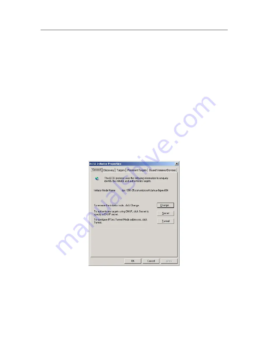
1).Double click MS iSCSI Initiator icon on the desktop. You can see an interface is shown as 

below. See Figure 10-1. 


Figure 10-1 

2) Click Discovery, you can see an interface is shown as in Figure 10-2. 

Содержание ESS3016X

Страница 1: ...ESS3016X Internet Intelligent Storage User s Manual...

Страница 2: ...llation 8 1 2 4 Cable Layout 9 1 2 5 Boot up and Shut down 10 2 SYSTEM OPERATION 13 2 1 Preparation Work 13 2 2 Network Setup 13 2 2 1 Set Controller IP Address 13 2 2 2 Network Connection Test 13 2 2...

Страница 3: ...ement 36 3 5 1 iSCSI Configuration 36 3 6 Share Management 37 3 6 1 Share configuration 38 3 6 2 FTP Configuration 43 3 6 3 Service Management 43 3 7 Status Management 44 3 7 1 Log Review 44 3 7 2 Ser...

Страница 4: ...6X 60 6 1 1 Disk Management 60 6 1 2 RAID Setup 61 6 2 iSCSI Management 63 6 2 1 iSCSI Setup 63 6 2 2 Share Management 64 7 APPENDIX A TERMS EXPLANATION 66 8 APPENDIX B DISK HOT SWAP OPERATION 68 9 AP...

Страница 5: ...using our internet intelligent storage system This operating manual is designed to be a reference tool for the installation and operation of your system Before installation and operation please read t...

Страница 6: ...installation 3 Qualified Engineers Needed All installation here should be done by the qualified engineers All the examination and repair should be done by the qualified service engineers We are not l...

Страница 7: ...ant Configuration Support 2 1 hot swap power Power Consumption 100V 240VAC 50Hz 60Hz Whole Unit Power Consumption 16 SATA HDDs 280W 350W Dimension H W D 133 450 650 mm Working Temperature 5 40 Working...

Страница 8: ...t to configure setup please follow the steps listed below z HDD installation Please refer to chapter 1 2 3 z Connect power cable and network cable Please refer to chapter 1 2 4 z Boot up device and ch...

Страница 9: ...Connect to mouse or keyboard to view device status 3 USB port Connect to USB device 4 COM Connect to RS232 COM to go to the command interface 5 CRT Port Connect to displayer 6 Ethernet port It is used...

Страница 10: ...NC normal close C public port AB RS485 alarm output G ground end Note Use special 1000M cable if your environment is 1000M 1 2 5 Boot up and Shut down 1 2 5 1 ESS3016X Please follow the steps listed...

Страница 11: ...channel to the power 11 HDD Read write Indication Light The blue light flashes when the system is reading or writing the HDD If you want to turn off unit power please follow the following steps z In w...

Страница 12: ...z Connect the device to the power z Connect the data cable to the unit z Boot up the unit skip this step if unit has boot up z Click unit power button to boot up ESS3015A You can see HDD channel read...

Страница 13: ...t mask 255 255 0 0 Admin password 888888888888 To configure 3016X internet intelligent storage device you need to set controller IP first 2 2 1 Set Controller IP Address Right click My Network Places...

Страница 14: ...88888888 Admin is the system administrator account and has the highest priority For security reasons please modify your password after first login At least 12 digit 2 2 3 3 Go to edit interface In the...

Страница 15: ...47 in the address column 10 6 5 47 is a new IP address you modified after you first logged in Input your user name and password you can log in After you logged in you can see an interface consisting...

Страница 16: ...oller configuration is Windows 2000 XP IE 6 0 or higher 3 2 System Management In this interface you can see the following six parts z Display system information z Parameter configuration z User manage...

Страница 17: ...bove threshold 55 or fan speed is below 1500r m system may display in red font to remind you Figure 3 2 3 2 2 Parameter Configuration Click parameter configuration button you can see the following int...

Страница 18: ...It can configure the whole system and set ordinary user share folder rights z Ordinary user it refers to all users except admin Ordinary user such as guest can modify its own password review and save...

Страница 19: ...FTP user there is no such a kind of requirement The iSCSI user can use the SAMBA NFS FTP service and the SAMBA NFS FTP user can use the iSCSI service only if its password is more than or equal to 12...

Страница 20: ...ce from system to guide you can see an interface is shown as in Figure 3 7 Note Please make sure there are 16 HDDs in current system and each HDD is free Otherwise system may pop up error prompt infor...

Страница 21: ...d then goes back to guide main interface See Figure 3 7 Figure 3 8 z In Figure 3 8 click next button System pops up a warning dialogue box to warn you Please click Yes button to continue Now you can s...

Страница 22: ...logue box to warn you Please click Yes button to continue Now you can see an interface is shown as in Figure 3 10 Figure 3 10 z In Figure3 10 click next button you can see an interface is shown as in...

Страница 23: ...3 13 Administrator can use this service to upgrade software After upgrading please reboot your system In Figure 3 13 the upgrade file located at E ESS_release 1 17 T General_ESS3016X_V1 17 T 071113 B...

Страница 24: ...e system reboot Figure 3 14 3 3 Network Management In this interface you can set device network card and router in the LAN 3 3 1 Network Configuration Click network configuration button you can see th...

Страница 25: ...button in you can see the following interface After your modification please click save button to exit See Figure 3 16 Figure 3 16 3 3 1 2 Status Click the status button in Figure 3 15 you can view cu...

Страница 26: ...formation If you want to view network card detailed information please click status button The interface is similar to Figure 3 17 If you want to configure the network card please click corresponding...

Страница 27: ...changed you may need to modify router setup such as add one router After setting 1 and 2 routers as default network card system default router setup and IP address are varying when network IP address...

Страница 28: ...e Figure 3 21 Here you can review the following information z Serial number z Channel number z Disk Name z Space z Status z Group name z Using status z Type Figure 3 21 3 4 1 1 HDD S M A R T informati...

Страница 29: ...il information You can click it to view more detail information in a new interface Click return button you can go back to Figure 3 21 Figure 3 22 3 4 1 2 Add hot spare disk In Figure 3 21 click add ho...

Страница 30: ...status is inactive z RAID1 and RAID5 support data restore function but it becomes usable after synchronization In Figure 3 25 you can get the following information z There are four RAID devices device...

Страница 31: ...disk You can refer to the amount displayed on the web 3 RAID 0 the total amount of N disk disk space disk amount You can refer to the amount displayed on the web Note If RAID device is synchronizing...

Страница 32: ...disk Insert disk this operation is also forbidden during the synchronization process You need to remove one disk if you want to insert a new one RAID begins new synchronization after inserting a new o...

Страница 33: ...3 4 2 2 Add RAID configuration Click add button you can see the following interface In Figure 3 28 administrator can select RAID type such as RAID0 and then select the member disk The damaged or used...

Страница 34: ...ol first and then you can remove the RAID group 3 4 3 Storage Pool Configuration In storage pool interface you can see the following interface See Figure 3 29 Here you can view the following informati...

Страница 35: ...nt you can view the corresponding remove button Note CIFS means SAMAB share mode and ftp means FTP share mode Figure 3 31 3 4 3 3 Remove Storage Pool The remove operation consists of the following two...

Страница 36: ...rst iSCSI share device for an example z The iSCSI share device name is iqn 2006 05 com dahuatec DVRch 20071108195910 among which DVRch1 is you self defined share folder name z The share folder target...

Страница 37: ...ated in pool The pool total space is 700G and used space is 35G z iSCSI device valid user is user1 3 5 1 2 Access iSCSI share You need to load iSCSI Initiator software to use iSCSI share function Ther...

Страница 38: ...the interface click add button You can see an interface is shown as in Figure 3 35 It is an interface for you to add share folder Here you can input the following information Pool name You can select...

Страница 39: ...there is no valid user all log in users can access current folder If there is valid user such as user1 other users can not access current folder 2 Add NFS share 1 Set share folder information 2 Enabl...

Страница 40: ...1 Set share folder information 2 Enable FTP share and then disable NFS and SAMBA share 3 Click save button 3 6 1 2 Edit share folder Click edit button after corresponding folder You can see an interf...

Страница 41: ...share service such as cifs nfs nfs ftp or cifs nfs ftp Access SAMBA share folder There are two ways for you to access SAMBA share folder z Web access In SAMBA click a SAMBA name from the share list an...

Страница 42: ...in Linux Use command to un install the mount umount home user home user Mount folder in Linux Access FTP share folder There are two ways for you to access FTP share folder z IE access Input 3016X int...

Страница 43: ...s you can use either or all of the methods to disable share z Delete share folder completely In share configuration interface See Figure 3 34 select the item from the share list and then click corresp...

Страница 44: ...ck start item and then click set button Disable FTP service check stop button and then click set button Restart FTP service check restart button and then click set button 3 6 3 4 iSCSI Configuration E...

Страница 45: ...ing the specific time period You can input a time period in the interface to search the log you want to view z System also supports log export function Figure 3 43 Click export button system pops up t...

Страница 46: ...3 45 In Figure 3 45 host IP address 10 6 5 49 is accessing SAMBA share folder Here you can also see accessing time Figure 3 45 3 7 3 Resume Resume interface is shown as in Figure 3 46 This function a...

Страница 47: ...47 3 8 Reboot Shut down You can see log out button in any interface It is on the top right corner See Figure 3 47 Click reboot button you can restart the device Click shutdown button you can turn off...

Страница 48: ...eation Figure 4 1 4 2 NAS Share Example 4 2 1 SAMBA Share Creation 4 2 1 1 Admin user login In the log in interface you can input administrator name and password to log in See Figure 4 2 Figure 4 2 De...

Страница 49: ...re 4 4 Please note system has three valid accounts z admin system administrator 8888888888 z guest ordinary user 666666666666 z ftpuser ftp user 111111111111 4 2 1 2 Create system user Here you can cr...

Страница 50: ...rom disk management select RAID configuration See Figure 4 6 Figure 4 6 And then click add button in Figure 4 7 Figure 4 7 You can see an interface is shown as in Figure 4 8 Here you can select RAID5...

Страница 51: ...4 8 Note Before using devices here please enable RAID5 device synchronization process 4 2 1 4 Storage pool configuration From disk management select storage pool configuration See Figure 4 9 Figure 4...

Страница 52: ...gure 4 10 Now you can configure storage pool See Figure 4 11 Here you can see raid5 device disk15 constitutes storage pool1 Figure 4 11 4 2 1 5 Share folder configuration From share management select...

Страница 53: ...a share folder such as pool z Input SAMBA share folder name DVRch6 z Set share folder total space 100G z Input share content description data from DVR channel 6 z Select a valid user such as user1 If...

Страница 54: ...ESS3016X User s Manual 54 Figure 4 14 4 2 1 6 Enable share service From share to service In Figure 4 15 you can enable SAMBA service and then click set button Figure 4 15 4 2 2 NFS Share Creation...

Страница 55: ...te share folder such as pool z Input NFS share folder name DVRch7 z Set share folder total space 100G z Input share description storage data from DVR channel 7 z Disable SAMBA share z Enable NFS share...

Страница 56: ...n and the step five FTP configuration See Figure 4 17 Figure 4 17 z FTP share folder configuration In Figure 4 18 you need to configure the following information 1 From the dropdown list select the po...

Страница 57: ...configuration In Figure 4 19 you need to set transmission speed connection amount of each IP and total connection amount Note IF there is created RAID device and storage pool you can create SAMBA NFS...

Страница 58: ...r steps are identical with SAMBA share of NAS share creation processes and the sixth step is also similar Here we just talk about the step five iSCSi configuration From iSCSI configuration select iSCS...

Страница 59: ...name DVRch4 z Set iSCSI total space 200G z Select one storage pool to create iSCSI share device Pool z Select valid user for iSCSI share device If you do not check a valid user here In the future whe...

Страница 60: ...s chapter we talk about how to extend ESS3016X internet intelligent storage device Though ESS3015A disk enclosure is an extensible device but for ESS3016X device it just adds some available disks in t...

Страница 61: ...nfiguration information by default You can click expand disk rack button to view corresponding information Please note though sometimes user interface just shows there is only disk rack1 you can not s...

Страница 62: ...e 6 4 Here you can select RAID type RAID0 RAID1 and RAID5 disk rack number host expand1 2 3 4 and then select disks to create a RAID device In this interface you can just see all the available disks t...

Страница 63: ...s are in expanding rack1 2 3 4 respectively Figure 6 5 z Add iSCSI Share Setup Before you create iSCSI share setup you need to create a storage pool first In Figure 6 5 click add button you can see an...

Страница 64: ...are device its name is test This iSCSI share device total capacity is 60G Select host system map all storage pool in host rack This iSCSI share device is created in host and its storage pool name is m...

Страница 65: ...ESS3016X User s Manual 65 Figure 6 7...

Страница 66: ...orage performance in RAID level RAID0 is to read write continue data in several HDD So system data query will be performed in several HDDs at the same time z RAID1 It is also called Mirror or mirrorin...

Страница 67: ...twork file system It is a distribution file system It can allow the local PC to use the file or peripheral devices of another PC It is mainly used in UNIX platform z iSCSI It is a abbreviation for int...

Страница 68: ...web configuration interface from disk management to RAID configuration you can see the corresponding RAID group status is clean degraded Operation example The RAID5 and RAID1 have the same hot swap op...

Страница 69: ...g out disk to be hot swapped In Figure 8 2 click edit button of the corresponding RAID device You can see an interface is shown as in Figure 8 3 Here you can see the following information z RAID 5 dev...

Страница 70: ...is in free status See Figure 8 4 Now there are two options z You can remove the disk1 from the rack z You can insert the disk1 into other RAID5 RAID1 in degraded mode And then create storage pool and...

Страница 71: ...ration interface from disk configuration to disk configuration you can see the RAID status information See Figure 8 6 Figure 8 6 8 from disk to RAID you can view the RAID device status after hot swap...

Страница 72: ...e there are four disks disk2 disk3 disk4 disk1 Now you can see the newly inserted disk name is disk1 3 In web configuration interface from disk configuration to disk information you can see the disk i...

Страница 73: ...dded disk information take disk volume as a symbol such as disk1 so in the step 2 please memorize hot swap disk name 6 In web configuration interface from disk configuration to disk configuration you...

Страница 74: ...configuration to RAID configuration you can see the following RAID device status See Figure 8 13 Figure 8 13 Note After hot swap RAID5 device status is from degrading to recovering and begins synchro...

Страница 75: ...artition Please follow the steps below 1 Access the SAMBA share of the 3016X internet intelligent storage device Open IE browser and input 3016X internet intelligent storage device IP address in the a...

Страница 76: ...l A Z and then click finish button Figure 9 3 3 View local PC disk Open my computer you can see network driver is not empty which means the map network drive is successful See Figure 9 4 Figure 9 4 No...

Страница 77: ...SI Initiator software Connect to iSCSi share of 3016X internet intelligent storage device via iSCSI Initiator Map iSCSI storage as local disk Partition and format the disk iSCSI Initiator software Ple...

Страница 78: ...intelligent storage device IP address and then click Ok button See Figure 10 3 Figure 10 3 4 Click target button to view 3016 internet intelligent storage device share situation See Figure 10 4 Here...

Страница 79: ...ESS3016X User s Manual 79 Figure 10 4 5 In Figure 10 4 select one iSCSI share and then click Log on button See Figure 10 5 Figure 10 5 Please enable auto connect function See Figure 10 6...

Страница 80: ...ser Click advance button system pops up a dialogue box Here you check CHAP logon information and then input user name and password Click OK you can access iSCSI share now See Figure 10 7 Figure 10 7 M...

Страница 81: ...016X User s Manual 81 Figure 10 8 2 In Figure 10 8 click disk 2 and then click initialize disk See Figure 10 9 Figure 10 9 3 Right click 12 00GB unallocated and then select new partition See Figure 10...

Страница 82: ...he instructions to set and format the disk 5 After formatting the iSCSI share will be displayed as newly added volume and has its own driver number See Figure 10 11 Now you can use iSCSI device Please...

Страница 83: ...dmin and password debug You can see an interface is shown as in Figure 11 1 It is a debug command line interface Figure 11 1 z Debug command operation Input command help after debug you can see an int...

Страница 84: ...in Figure 11 3 You can see the information after bond0 In Figure 11 3 you can see system IP address is 10 6 5 81 Note Netset is to reset system IP address and it has two command parameters parameter...

Страница 85: ...User s Manual 85 Figure 11 3 Slight difference may be found in user interface All the designs and software here are subject to change without prior written notice Please visit our website for more inf...

Отзывы: