User’s Manual
1
Table 1-1 Access ANPR kit structure
No.
Description
No.
Description
1
Microphone
7
Speaker
2
Intercom button
8
Access ANPR camera
3
Mainboard
9
Universal joint
4
Wiring board
10
LED display
5
Power
11
Base
6
Earth leakage circuit breaker (ELCB)
—
—
Ports
1.3
1.3.1 Control Panel Ports
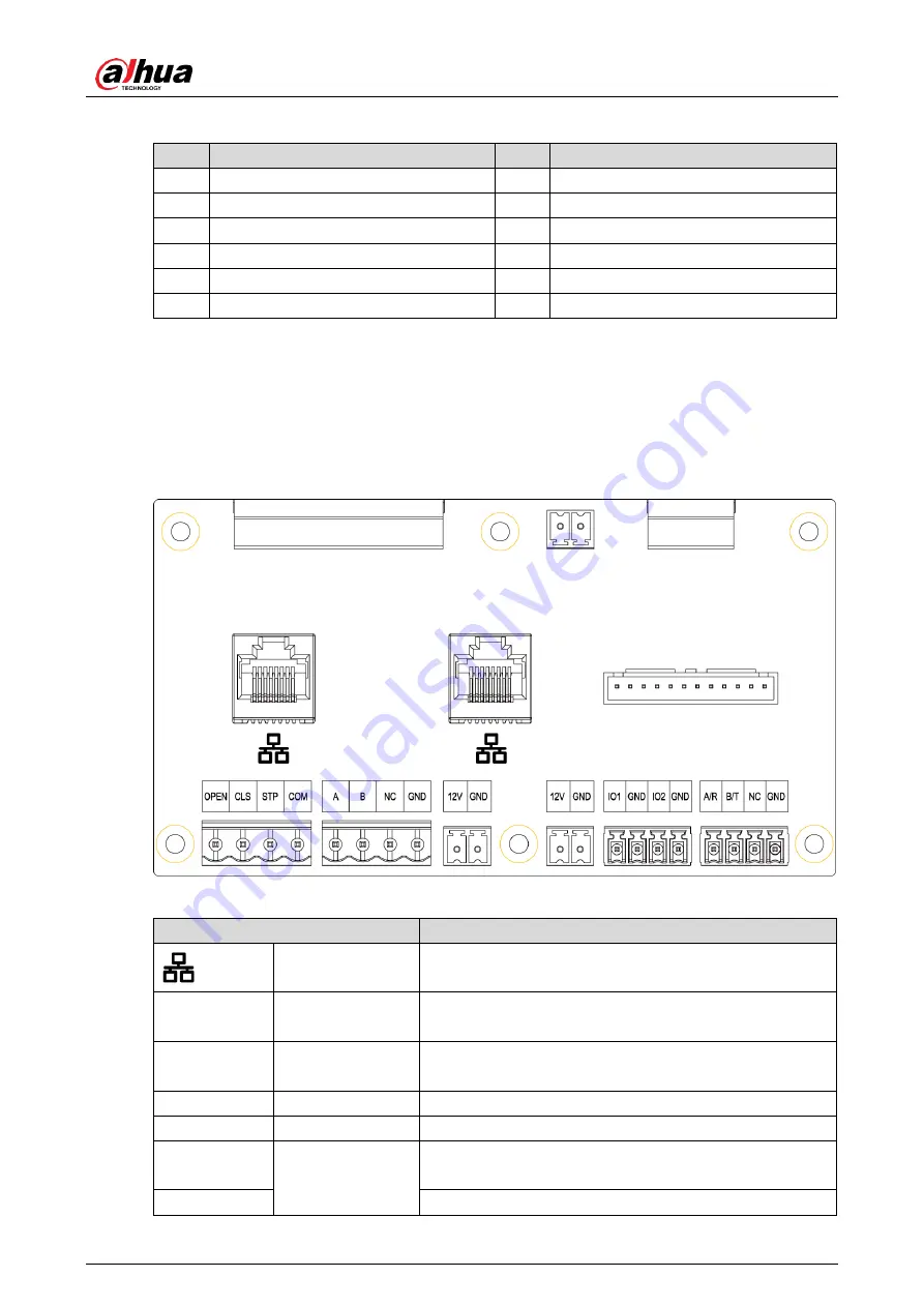
Control panel ports
Figure 1-4
Table 1-2 Control panel port description
Interface
Description
Ethernet port
Connect to standard Ethernet cable.
OPEN, CLS,
STP, COM
—
Alarm output, control the open, close or stop running of
barrier.
A, B
RS-485
RS-485_A and RS-485_B, connecting to the LED
display.
NC
—
No connection.
GND
—
Grounding connection.
12 V DC
Power
port
(inside the Kit)
12 V DC power output port, supplying power for
external device.
GND
Ground terminal.


