Motor control:
Each of the 4 motors on the robot are driven by a “H” bridge. This is a circuit commonly used to control DC
motors when direction as well as speed needs to be controlled.
F
ield
E
ffect
T
ransistors (FET) are used on
this robot as they are more efficient than
B
i-polar
J
unction
T
ransistors (BJT) thus allowing more power to be
delivered to the motors. Each “H” bridge includes a current sensing circuit to allow the robot to monitor the
current being drawn by a motor and each motor has a simple optical encoder to measure rotation.
Each motor has 2 processor pins dedicated to control and another 2 dedicated to feedback. These pins are
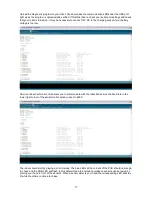
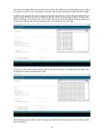
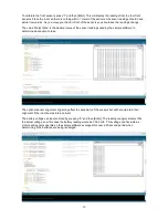
defined in the “IOpindefinitions.h” tab. Using the left motor as an example:
Lmotordirpin
controls the direction of the left motor. When this pin is HIGH or “1” then the left wheels will
run forward. Making this pin LOW or “0” will cause the left wheels of the robot to run in reverse.
Lmotorpwmpin
controls the speed of the left motor using
P
ulse
W
idth
M
odulation (PWM). The Arduino IDE
uses the command analogWrite() to generate PWM using values from 0 to 255. A value of 0 will cause the
motor to stop completely. A value of 255 will run the motor at full power.
At low speeds the motor may stall. A simple method of preventing the motor from stalling at low speed is
alternate it’s speed between the speed you want and a low value that will not stall. For example, if you want
a speed of 23 and you know the motor will not stall at speeds of 60 and higher then write your program so
that at speeds below 60 the program will alternate the speed between the desired speed and 60.
This will cause the motors power to pulse at a level that can overcome a stall. While the robots movements
will not be as smooth it will allow the robot to achieve much lower speeds.
Lmotorencpin
is the digital signal from the motors optical encoder. The encoder reads black and white
marks on the motor gear train and outputs a “1” when a black mark is read and a “0” when a white mark is
read. In the sample software, external interrupts are used to monitor these pins and count when they change
states.
As this encoder cannot determine direction the sample software uses the direction the motor is travelling in
to determine if it should add or subtract from a value. If the motor needs to change direction then it should be
allowed to come to a complete stop first to ensure an accurate count.
Lmotorcurpin
is an analog signal that represents the current being drawn by the motor. Using the
analogRead() command in the Arduino IDE will give a value of approximately 400 when the motor is drawing
1A. This can be useful not only for determining if the motor has stalled but also if the robot needs
maintenance. If for example dust or dirt gets into the gears then the robot may continue to operate but the
average current draw of the motor will increase. If the motor draws less current than expected then perhaps
the robot has fallen so that the left wheels can spin without load.
Amotorlimpin
and
Gmotorlimpin
are the digital input pins for the Arm and Gripper limit switches. The digital
inputs are normally held at 1 or HIGH by internal pullup resistors. A low or 0 indicates that a switch is closed.
Using motor feedback:
By monitoring the encoders and current sensors of the robots motors various functions can be achieved. The
wheel encoders allow the robot to measure speed and distance travelled allowing the robot to make a map of
an area to improve navigation. Current sensing of the wheel motors in conjuction with the encoder
information allows the robot to map inclines such as ramps.
Monitoring the current draw of the arm motor when lifting an object can be used to judge the weight of an
object and determine if the gripper needs to apply more pressure to hold the object.
Using the arm encoder to determine if the arm is moving or has stalled as the motor current for a heavy
object might be similar to the stall current.
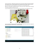
The gripper encoder allows the robot to estimate the size of the object and the gripper motors current draw
can be used to determine how much pressure is being applied.
14
Содержание MR. Tidy
Страница 3: ...Main board Features 3...


