background image

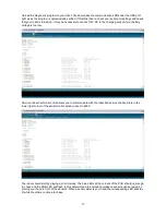
Upload the diagnostic program to your robot. You should see the communication LEDs near the USB port 
light up as the program is uploaded and verified. If this fails then re-check your serial port settings and check 
that your robot is turned on. It may be necessary to connect 12V DC to the charging socket if your battery 
voltage is too low.

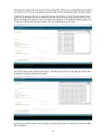
Now run the serial monitor, this allows you to communicate with the robot. Make sure the baud rate in the 
lower right corner of the serial monitor window is set to 9600.

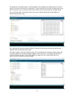
The robot should start by playing a short melody. The blue LEDs at the corners of the PCB should now begin 
to chase and the RGB LED will flash. In this default mode the collision avoidance sensors can be tested by 
placing your hand in front of the sensors. When a sensor detects your hand the corresponding LED will stay 
lit while the others continue to chase. 

17

Содержание MR. Tidy

Страница 1: ...ic platform ideal for students and hobbyist alike The 2DOF arm and array of sensors make this robot capable of so much more than just line following and object avoidance An open framework makes experi...

Страница 2: ...Contents Main board features Assembly Installing the software Understanding the sample software How it works Trouble shooting Using the diagnostic software Specifications 3 4 9 10 13 15 16 21 2...

Страница 3: ...Main board Features 3...

Страница 4: ...arm is attached to the base Start by removing the nuts and spring washers shown in the photo bellow Do not completely remove the screws This will allow you to use a screwdriver to join the two sectio...

Страница 5: ...brass spacers and remove the main board STEP 4 Insert 6x AA UM3 NiMh batteries Do not use alkaline batteries as they cannot supply enough power for the robot and cannot be recharged Note how the batte...

Страница 6: ...ure the battery cable is behind the mounting post so it cannot jam in the gears STEP 6 Mount the arm onto the base with 3x8mm screws as shown The screwdriver goes between the gears from above It may b...

Страница 7: ...STEP 7 Now that the arm is mounted we need to tie the wires to the frame and connect all the wires to the main board Pay careful attention to the orientation of the plugs 7...

Страница 8: ...nection may damage the receiver STEP 9 Check your connections carefully before turning the robot on When you turn it on it should start by playing a simple tune The robot will then open its gripper lo...

Страница 9: ...to program we have chosen to make it compatible with the Arduino IDE and have included a USB interface This manual assumes that the Arduino IDE version 18 or later is being used Although the robot co...

Страница 10: ...rduino programming environment as this is easier for beginners You will see several tabs at the top these tabs help organise the program making it easier to use The first tab shows you the main progra...

Страница 11: ...n here This is basically a scribble page The fourth tab contains a list of constants Normally these values do not change They are listed here to simplify program adjustments such as calibration of the...

Страница 12: ...begin operation The loop function is the main core of the program and repeats continuously until the robot is shutdown or reset This function can be broken into several steps 1 Check the timer and ch...

Страница 13: ...h their IR LED Unlike the front sensors these LEDs are individually controlled allowing the visible LEDs to be used to display patterns or the status of the robot This does not interfer with object de...

Страница 14: ...is read and a 0 when a white mark is read In the sample software external interrupts are used to monitor these pins and count when they change states As this encoder cannot determine direction the sa...

Страница 15: ...ght With the gripper and arm encoders check that the encoder disk is as close as possible to the encoder PCB Load the diagnostic program and connect 12V DC to the recharging socket Check the encoder w...

Страница 16: ...have the Arduino Programming Environment loaded on your computer version 18 or later Open the program Mr_Tidy_PCB_diagnostic Go to the tools menu and select the Arduino Mega as your board type Make s...

Страница 17: ...o low Now run the serial monitor this allows you to communicate with the robot Make sure the baud rate in the lower right corner of the serial monitor window is set to 9600 The robot should start by p...

Страница 18: ...ues in the constants tab and then upload the program again When the red green and blue readings on the serial monitor are the same then the sensor is calibrated Write these values down so they can be...

Страница 19: ...eadings used by the sample software to determine what action to take The optional sensor alignment rings may affect the sensitivity of the sensors but will help maintain their alignment if the robot b...

Страница 20: ...wheels are not in contact with the ground Below you can see a photo of the gripper motor with it s drive gear removed Remember the arm and gripper motors have two gears that need to be removed If you...

Страница 21: ...frequency 38KHz Motor control 4x FET H bridges rated at 4A continuous with current sensing Position feedback 2x Wheel encoder resolution 24 counts per revolution 1x Arm encoder resolution 27 counts p...

Отзывы: