S0708315K
Page 33
Main Pump (Kawasaki)
Negative Flow Control
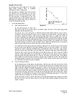
By changing the pilot pressure Pi, the pump
tilting angle (delivery flow) is regulated
arbitrarily, as shown in Figure 24.
This regulator is a negative flow control in which
the delivery flow Q decreases as the pilot
pressure Pi rises. With this mechanism, when
the pilot pressure corresponding to the flow
required for the work is commanded, the pump
discharges the required flow only, so it does not
consume unnecessary power.
1.
Functional Explanation
A.
Flow reducing Function
As the pilot pressure Pi rises, the
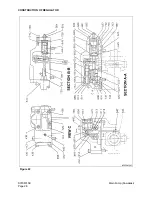
pilot piston (643) moves to the right to a position where the force of the pilot spring (646)
balances with the hydraulic force.
The groove (A) in the pilot piston is attached with pin (875) that is fixed to lever 2 (613).
Therefore, when the pilot piston moves, lever 2 rotates around the fulcrum of point B (fixed by
the fulcrum plug (614) and pin (875). Since the large-hole section (C, Figure 23) of lever 2
contains a protruding pin (897) fixed to the feedback lever(611), the pin (897) moves to the right
as lever 2 rotates. Since the opposing-flat section (D) of the feedback lever is attached with the
pin (548) fixed by the tilting pin (531) that swings the swash plate, the feedback lever rotates
around the fulcrum of point D, as the pin (897) moves. Since the feedback lever is connected
with the spool (652) via the pin (874), the spool moves to the right.
The movement of the spool causes the delivery pressure P1 to connect to port C liter through
the spool and to be admitted to the large-diameter section of the servo position. The delivery
pressure P1 that is constantly admitted to the small-diameter section of the servo piston moves
the servo piston to the right due to the area difference, resulting in decrease of the tilting angle.
When the servo piston moves to the right, point D also moves to the right. The spool is fitted
with the return spring (654) and is tensioned to the left at all times, and so the pin (897) is
pressed against the large-hole section (C) of lever2. Therefore, as point D moves, the feedback
lever rotates around the fulcrum of point C, and the spool is shifted to the left. This causes the
opening between the sleeve (651) and spool (652) to close slowly, and the servo piston comes
to a complete stop when it closes completely.
B.
Flow Increasing Function
As the pilot pressure Pi decreases, the pilot piston (643) moves to the left by the action of the
pilot spring (646) and causes lever 2 (613) to rotate around the fulcrum of point B. Since the pin
(897) is pressed against the large-hole section (C) of lever 2 by the action of the return spring
(654) via the spool (652), pin (874), and feedback lever (611), the feedback lever rotates around
the fulcrum of point D as lever 2 rotates, and shifts the spool to the left. Port C liter opens a way
to the tank port as the spool moves. This deprives the large-diameter section of the servo piston
of pressure, and shifts the servo piston to the left by the discharge pressure P1 in the small-
diameter section, resulting in an increase in the flow rate.
As the servo piston moves, point D also moves to the left, the feedback lever rotates around the
fulcrum of point C, and the spool moves to the right till the opening between the spool and
sleeve is closed.
Figure 24
Содержание Solar 300LC-V
Страница 2: ......
Страница 4: ......
Страница 7: ...1SAFETY...
Страница 8: ......
Страница 46: ...S0102000 Page 38 Track Excavator Safety...
Страница 47: ...1SPECIFICATIONS...
Страница 48: ......
Страница 54: ...S0202080K Page 6 Specifications for Solar 300LC V...
Страница 70: ...S0202080K Page 22 Specifications for Solar 300LC V...
Страница 71: ...1GENERAL MAINTENANCE...
Страница 72: ......
Страница 86: ...S0302000 Page 14 General Maintenance Procedures Return to Master Table of Contents...
Страница 99: ...1UPPER STRUCTURE...
Страница 100: ......
Страница 102: ...S0402040K Page 2 Cab TABLE OF CONTENTS Removal 3 Installation 6...
Страница 110: ...S0403050K Page 2 Counterweight Return to Master Table of Contents TABLE OF CONTENTS General 3 Removal 5 Installation 7...
Страница 116: ...S0403050K Page 8 Counterweight Return to Master Table of Contents...
Страница 120: ...S0405110K Page 4 Fuel Tank PARTS LIST 3 7 5 6 4 10 9 23 8 12 11 1 13 16 19 20 14 34 33 ARS1660L Figure 1...
Страница 140: ...S0407000 Page 6 Swing Bearing...
Страница 164: ...S0408070K Page 24 Swing Reduction Gear...
Страница 165: ...1LOWER STRUCTURE AND CHASSIS...
Страница 166: ......
Страница 190: ...S0505000 Page 24 Track Assembly 7 Tighten plug 1 Figure 48 Figure 48...
Страница 191: ...S0505000 Page 25 Track Assembly TRACK SPRING AND TRACK ADJUSTING CYLINDER PARTS LIST Figure 49...
Страница 193: ...1ENGINE AND DRIVE TRAIN...
Страница 194: ......
Страница 205: ...S0605060K Page 11 Air Conditioner Face and Defroster ARS1300L Figure 12...
Страница 220: ...S0605060K Page 26 Air Conditioner...
Страница 229: ...1HYDRAULICS...
Страница 230: ......
Страница 262: ...S0703010K Page 2 Accumulator TABLE OF CONTENTS General Description 3 Specifications 4...
Страница 266: ...S0703010K Page 6 Accumulator...
Страница 274: ...S0704080K Page 8 Center Joint Swivel...
Страница 283: ...S0705000 Page 9 Cylinders...
Страница 286: ...S0705000 Page 12 Cylinders P S Power Steering O R Out Rigger MODEL CYLINDER A 0 1 B C D MODEL CYLINDER...
Страница 287: ...S0705000 Page 13 Cylinders...
Страница 291: ...S0705000 Page 17 Cylinders...
Страница 296: ...S0705000 Page 22 Cylinders SLIPPER SEAL JIG ARS4770L A 2 A A 14 B B 40 5 R 1 0 R1 1 0 Figure 10...
Страница 299: ...S0705000 Page 25 Cylinders...
Страница 300: ...S0705000 Page 26 Cylinders SLIPPER SEAL STRAIGHTENING JIG ARS4780L 2 R1 50 25 100 A 15 A 2 5 R 2 C 1 Figure 11...
Страница 308: ...S0705000 Page 34 Cylinders 17 Force out pin bushing 1 from body of cylinder Figure 28...
Страница 312: ...S0705000 Page 38 Cylinders...
Страница 324: ...S0707270K Page 12 Swing Motor Toshiba MFC200 PARTS LIST Figure 6...
Страница 355: ...S0707315K Page 11 Travel Motor with Gearbox...
Страница 361: ...S0707315K Page 17 Travel Motor with Gearbox JIG 7 JIG 8 JIG 9 JIG 10 JIG 11 JIG 12 ARS4000L Figure 14...
Страница 362: ...S0707315K Page 18 Travel Motor with Gearbox JIG 13 JIG 14 JIG 15 JIG 17 JIG 18 ARS4010L JIG 19 20 JIG 16 Figure 15...
Страница 424: ...S0708315K Page 28 Main Pump Kawasaki CONSTRUCTION OF REGULATOR Figure 22...
Страница 444: ...S0708315K Page 48 Main Pump Kawasaki...
Страница 450: ...S0709401K Page 6 Main Control Valve Kayaba Figure 1...
Страница 451: ...S0709401K Page 7 Main Control Valve Kayaba Figure 2...
Страница 453: ...S0709401K Page 9 Main Control Valve Kayaba...
Страница 455: ...S0709401K Page 11 Main Control Valve Kayaba Figure 4...
Страница 467: ...S0709401K Page 23 Main Control Valve Kayaba Figure 16...
Страница 500: ...S0709401K Page 56 Main Control Valve Kayaba Figure 54...
Страница 548: ...S0792160K Page 2 Hydraulic Schematic S300LC V TABLE OF CONTENTS General Description 3 Solar 300LC V 4...
Страница 552: ...S0792160K Page 6 Hydraulic Schematic S300LC V...
Страница 553: ...1ELECTRICAL SYSTEM...
Страница 554: ......
Страница 608: ...S0802220K Page 54 Electrical System...
Страница 627: ...S0802220K Page 73 Electrical System...
Страница 632: ...S0892160K Page 2 Electrical Schematic S300LC V TABLE OF CONTENTS General Description 3 Solar 300LC V 4...
Страница 634: ...S0892160K Page 4 Electrical Schematic S300LC V SOLAR 300LC V Figure 2...
Страница 636: ...S0892160K Page 6 Electrical Schematic S300LC V...
Страница 637: ...1ATTACHMENTS...
Страница 638: ......
Страница 653: ...S0904005K Page 7 Bucket 5 Roll the new O ring 1 Figure 9 into the O ring groove ARO1392L 1 Figure 9...
Страница 658: ......


