S0102000
Page 18
Track Excavator Safety
ENGINE STARTING
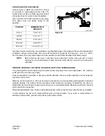
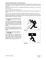
Walk around your machine before getting in the operator’s cab. Look for evidence of leaking fluid, loose
fasteners, misaligned assemblies or any other indications of possible equipment hazard.
All equipment covers and machinery safety guards must be in place, to protect against injury while the
machine is being operated.
Look around the work site area for potential hazards, people or properly that could be at risk while
operation is in progress.
NEVER start the engine if there is any indication that maintenance or service work is in progress, or if a
warning tag is attached to controls in the cab.
A machine that has not been used recently, or is being operated in extremely cold temperatures, could
require a warm-up or maintenance service before start-up.
Check gauges and monitor displays for normal operation before starting the engine. Listen for unusual
noises and remain alert for other potentially hazardous conditions at the start of the work cycle.
Do not short circuit the starting motor to start the engine. This is not only dangerous, but may also damage
the machine.
When starting the engine, sound the horn as an alert.
Start and operate the machine only while seated.
BEFORE OPERATING MACHINE
If checks are not carried out properly after starting the engine, it may result in a delay in discovering
abnormalities in the machine, and this may lead to personal injury or damage to the machine.
Carry out the checks in an open area where there are no obstructions. Do not let anyone near the machine
when carrying out the checks.
•
Check the operating condition of the equipment, and the actuation of the bucket, arm, boom,
travel, and swing systems.
•
Check the machine for any abnormal noise, vibration, heat, smell, or abnormality with the
gauges. Check also for leakage of air, oil, and fuel.
•
If any abnormality is found, repair the problem immediately. If the machine is used without
repairing the problems, it may lead to unexpected injury or failure.
•
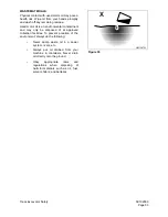
Clear all personnel from directly around machine and from the area.
•
Clear all obstacles from the machine's path. Beware of hazards.
•
Be sure that all windows are clean. Secure the doors and the windows in the open position or in
the shut position.
•
Adjust the rear view mirrors for best visibility close to the machine. Make sure that the horn, the
travel alarm (if equipped), and all other warning devices are working properly.
•
Fasten the seat belt securely.
•
Warm up the engine and hydraulic oil before operating machine.
•
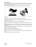
Before moving the machine, check the position of undercarriage. The normal travel position is
with idler wheels to the front under the cab and the drive sprockets to the rear. When the
undercarriage is in the reversed position, the travel controls must be operated in opposite
directions.
Содержание Solar 300LC-V
Страница 2: ......
Страница 4: ......
Страница 7: ...1SAFETY...
Страница 8: ......
Страница 46: ...S0102000 Page 38 Track Excavator Safety...
Страница 47: ...1SPECIFICATIONS...
Страница 48: ......
Страница 54: ...S0202080K Page 6 Specifications for Solar 300LC V...
Страница 70: ...S0202080K Page 22 Specifications for Solar 300LC V...
Страница 71: ...1GENERAL MAINTENANCE...
Страница 72: ......
Страница 86: ...S0302000 Page 14 General Maintenance Procedures Return to Master Table of Contents...
Страница 99: ...1UPPER STRUCTURE...
Страница 100: ......
Страница 102: ...S0402040K Page 2 Cab TABLE OF CONTENTS Removal 3 Installation 6...
Страница 110: ...S0403050K Page 2 Counterweight Return to Master Table of Contents TABLE OF CONTENTS General 3 Removal 5 Installation 7...
Страница 116: ...S0403050K Page 8 Counterweight Return to Master Table of Contents...
Страница 120: ...S0405110K Page 4 Fuel Tank PARTS LIST 3 7 5 6 4 10 9 23 8 12 11 1 13 16 19 20 14 34 33 ARS1660L Figure 1...
Страница 140: ...S0407000 Page 6 Swing Bearing...
Страница 164: ...S0408070K Page 24 Swing Reduction Gear...
Страница 165: ...1LOWER STRUCTURE AND CHASSIS...
Страница 166: ......
Страница 190: ...S0505000 Page 24 Track Assembly 7 Tighten plug 1 Figure 48 Figure 48...
Страница 191: ...S0505000 Page 25 Track Assembly TRACK SPRING AND TRACK ADJUSTING CYLINDER PARTS LIST Figure 49...
Страница 193: ...1ENGINE AND DRIVE TRAIN...
Страница 194: ......
Страница 205: ...S0605060K Page 11 Air Conditioner Face and Defroster ARS1300L Figure 12...
Страница 220: ...S0605060K Page 26 Air Conditioner...
Страница 229: ...1HYDRAULICS...
Страница 230: ......
Страница 262: ...S0703010K Page 2 Accumulator TABLE OF CONTENTS General Description 3 Specifications 4...
Страница 266: ...S0703010K Page 6 Accumulator...
Страница 274: ...S0704080K Page 8 Center Joint Swivel...
Страница 283: ...S0705000 Page 9 Cylinders...
Страница 286: ...S0705000 Page 12 Cylinders P S Power Steering O R Out Rigger MODEL CYLINDER A 0 1 B C D MODEL CYLINDER...
Страница 287: ...S0705000 Page 13 Cylinders...
Страница 291: ...S0705000 Page 17 Cylinders...
Страница 296: ...S0705000 Page 22 Cylinders SLIPPER SEAL JIG ARS4770L A 2 A A 14 B B 40 5 R 1 0 R1 1 0 Figure 10...
Страница 299: ...S0705000 Page 25 Cylinders...
Страница 300: ...S0705000 Page 26 Cylinders SLIPPER SEAL STRAIGHTENING JIG ARS4780L 2 R1 50 25 100 A 15 A 2 5 R 2 C 1 Figure 11...
Страница 308: ...S0705000 Page 34 Cylinders 17 Force out pin bushing 1 from body of cylinder Figure 28...
Страница 312: ...S0705000 Page 38 Cylinders...
Страница 324: ...S0707270K Page 12 Swing Motor Toshiba MFC200 PARTS LIST Figure 6...
Страница 355: ...S0707315K Page 11 Travel Motor with Gearbox...
Страница 361: ...S0707315K Page 17 Travel Motor with Gearbox JIG 7 JIG 8 JIG 9 JIG 10 JIG 11 JIG 12 ARS4000L Figure 14...
Страница 362: ...S0707315K Page 18 Travel Motor with Gearbox JIG 13 JIG 14 JIG 15 JIG 17 JIG 18 ARS4010L JIG 19 20 JIG 16 Figure 15...
Страница 424: ...S0708315K Page 28 Main Pump Kawasaki CONSTRUCTION OF REGULATOR Figure 22...
Страница 444: ...S0708315K Page 48 Main Pump Kawasaki...
Страница 450: ...S0709401K Page 6 Main Control Valve Kayaba Figure 1...
Страница 451: ...S0709401K Page 7 Main Control Valve Kayaba Figure 2...
Страница 453: ...S0709401K Page 9 Main Control Valve Kayaba...
Страница 455: ...S0709401K Page 11 Main Control Valve Kayaba Figure 4...
Страница 467: ...S0709401K Page 23 Main Control Valve Kayaba Figure 16...
Страница 500: ...S0709401K Page 56 Main Control Valve Kayaba Figure 54...
Страница 548: ...S0792160K Page 2 Hydraulic Schematic S300LC V TABLE OF CONTENTS General Description 3 Solar 300LC V 4...
Страница 552: ...S0792160K Page 6 Hydraulic Schematic S300LC V...
Страница 553: ...1ELECTRICAL SYSTEM...
Страница 554: ......
Страница 608: ...S0802220K Page 54 Electrical System...
Страница 627: ...S0802220K Page 73 Electrical System...
Страница 632: ...S0892160K Page 2 Electrical Schematic S300LC V TABLE OF CONTENTS General Description 3 Solar 300LC V 4...
Страница 634: ...S0892160K Page 4 Electrical Schematic S300LC V SOLAR 300LC V Figure 2...
Страница 636: ...S0892160K Page 6 Electrical Schematic S300LC V...
Страница 637: ...1ATTACHMENTS...
Страница 638: ......
Страница 653: ...S0904005K Page 7 Bucket 5 Roll the new O ring 1 Figure 9 into the O ring groove ARO1392L 1 Figure 9...
Страница 658: ......


