background image

DAC Monitoring and Control System 

                 User Manual Data Logger and Tower Meter 


DL-PDL_General-User-Manual

_ve_2-0-2.docx


Page 71


12  Environment 

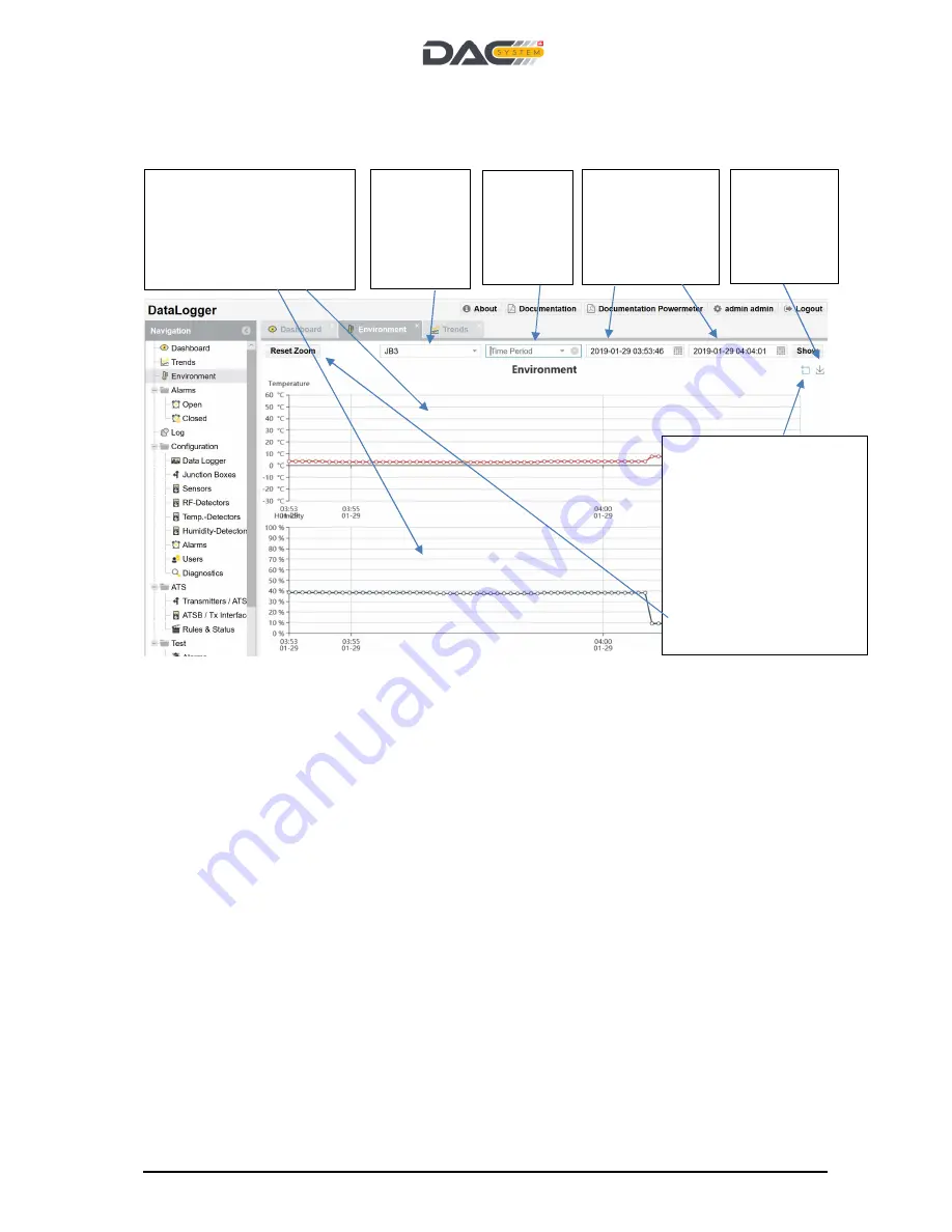
Environmental data are stored in the same way as the sensor data. 


Choice of 
JB with 
related 
Environme
ntal 
sensors. 

After clicking the 

blue


field, the user can mark 
from left to right a zoom 
in field. The user can 
repeat this action until he 
finds the right spot of 
interest.  
To reset to the original 
scaling 
Click the “reset zoom” on 
the upper left side. 

Use this 
button to 
export the 
graph in a 
png file. 

Select 
pre-
defined 
time 
windows. 

Inside the graph the 
mouse can move to the 
point of interest (monitor 
line), time and effective 
measured values are 
displayed. 

Select Start and 
Stop date and 
time to search 
for a specific 
data. 

Содержание Data Logger v2 Series

Страница 1: ...ng and Control System Customers File DL PDL_General User Manual_ve_2 0 2 docx Pages 91 Abstract This user manual helps the operator to install and configure the Data Logger and Tower Meter as part of...

Страница 2: ...cuits Operating Personnel must always follow general safety precautions Personnel do not replace components or adjust the inside of the equipment with high voltage supply turned on To avoid accidents...

Страница 3: ...ontrol System 19 9 1 Get started 19 9 2 Principle user interaction 21 9 3 Configuration of the DL PDL 22 9 3 1 General 22 9 3 2 Maintenance Mode configuration 23 9 3 3 NTP configuration 24 9 3 4 LAN c...

Страница 4: ...5 ATSB Tx Interface 84 14 6 ATSB Interface 86 14 7 Rules Status 87 14 8 ATS Dashboard view 91 15 Tower Meter Touch Screen Interface 93 15 1 Dashboard 93 15 2 Trend Chart 94 15 3 Alarms 94 15 4 SMART C...

Страница 5: ...ease 1 2 21 Version 1 1 0 and is able to communicate with the Analytics SW 1 3 0 Release 10 07 2017 Christian Brand Supports JB3 x JB4 x RF and Temp Detector Version 1 1 0 and is able to communicate w...

Страница 6: ...sensor or rf detector signal SNMP Simple Network Management Protocol NMC Network Management Centre or Network Operation Centre NOC ATS Automatic Transmitter Switch function SMART Control ATSS Automati...

Страница 7: ...party or outsourced services by detecting power level and measure return loss VSWR Increase the safety of the RF system by controlling the transmitters with 4 1 Purpose of the Document This user manua...

Страница 8: ...Logger and Tower Meter DL PDL_General User Manual_ve_2 0 2 docx Page 8 Out of scope of this manual is the set up and going life of the Analytics SW or the detailed instruction of the installation pro...

Страница 9: ...res an Ethernet IP connection to connect either to the DL PDL directly or for the communication with the Analytics SW If no Ethernet connection is available a mobile data connection via GSM can be use...

Страница 10: ...rature at indoor monitoring points 2 Junction Box Various versions JB The sensors RF Temp detectors are connected with a jumper cable to the JB the JB is available in different versions The JB can wor...

Страница 11: ...to increase the safety of the RF installation SMART Control is fast reliable and operates with multiple decision criteria Criteria are alarms detected on threshold of available monitoring points conne...

Страница 12: ...7 Special tools For the correct installation of the hybrid connector Han Brid the following tools are required Tool Supplier Part No Comment Crimptool Harting Crimp tool Harting for Han Brid electrica...

Страница 13: ...SIM card for mobile data transfer In case a local WLAN Wi Fi connection is required the corresponding option needs to be ordered Commissioning for the commissioning of the system the sensor and the J...

Страница 14: ...e should be connected to the USP Uninterruptible Power Supply if available If no USP is available both power supplies are connected to the local AC power available This will prevent the Monitoring sys...

Страница 15: ...terface to connect to operator data network IO Interface Local Ethernet port to connect the Laptop Status LED Green Operating DL is powered and SW system is up and running Red Alarm the DL has an alar...

Страница 16: ...ng system and the application 8 5 I O Interface Ports Pin Function Description RS 232 Sub D9 f Connector 1 12V 2 Output A Output active 12V 100mA 3 Output B 4 Input A Ground connection 5mA will trigge...

Страница 17: ...alled in the right position of the CPU board The module works in parallel with a mobile data or LAN connection GSM module SSD Disk Per default the configuration are as follows SSID dacs datalogger Pas...

Страница 18: ...DAC Monitoring and Control System User Manual Data Logger and Tower Meter DL PDL_General User Manual_ve_2 0 2 docx Page 18...

Страница 19: ...port Start your internet explorer Enter the following IP address to in the URL field 192 168 1 1 Enter your password default password Username admin Password admin Username user Password user The DL...

Страница 20: ...on to change the password after the first login immediately Select User Select New Add User Profiles Add user profile the email address and mobile number are only used for the function password forgot...

Страница 21: ...h the page content press F5 Select subject out of the navigation tree If a subject is selected the tab opens up the user can directly switch between the tabs Login Information Command button Edit Dele...

Страница 22: ...system generates a unique ID for this DL PDL With this button the configuration information of all system elements are exported into a pdf file which can be printed or stored for documentation reason...

Страница 23: ...format Grad 1 3 digits decimal value representing minutes seconds up to 8 digits google format for conversion use http www csgnetwork com gpscoordconv html JB PDL polling rate shortest time 4 seconds...

Страница 24: ...s to be set initially to warrant correct data logging and time stamps 9 3 4 LAN configuration 1 Default a public NTP server is configured in case the DL PDL is part of the corporate intranet the IP ad...

Страница 25: ..._General User Manual_ve_2 0 2 docx Page 25 If the LAN port is activated the MAC address is displayed Select DHCP or Static IP addressing and add related configurations click Save button after changing...

Страница 26: ...ent Which alarm is forwarded can be configured in Alarm menu Enter the mobile number of the alarm message recipient make sure that the format follows the international requirements In the transport fi...

Страница 27: ...connection information and close the DL PDL configuration menu Open the DL PDL configuration menu again and check for the IP address IP address If the mobile connection is working an IP address is sho...

Страница 28: ...tem ch Caution Make sure the RVTS is subscribed from DAC System to have the service available in time 9 3 7 SMTP configuration Default parameters are using email server SMTP Change email account param...

Страница 29: ...of the monitoring points sensors rf detectors etc Alarms can be collected if in the alarm configuration menu the alarm forwarding via SNMP is activated Details are described in the MIB Both activities...

Страница 30: ...yption methods Enter user name password and encryption key of the connecting NMS OMS system SNMP Manager For the transport UDP or TCP is selected If the SNMP manager is supporting TCP this is the pref...

Страница 31: ...DAC Monitoring and Control System User Manual Data Logger and Tower Meter DL PDL_General User Manual_ve_2 0 2 docx Page 31 PTx und PRx in Watt Return Loss in dB VSWR has no measurement unit...

Страница 32: ...p is sent again 9 3 9 Analytics configuration If the Analytics SW is installed after the DL PDL it is possible to upload the data to Analytics acc to this table An import of 30 days of data easily can...

Страница 33: ...lt URL the default URL is the DAC System Update Link Internet Always the latest released version of the DL PDL SW is available This link can be used if the DL PDL is connected to the public internet o...

Страница 34: ...nk works only if a local web service is installed with latest DL PDL SW Note 1 An update via weblink is only possible if the DL PDL has access to the public internet and to the Monitoring System Updat...

Страница 35: ...ports are presented as follows The PDL 3 x 4 x SMA RF input ports are presented as RF Detectors the RJ45 interface is initially presented as sensor but can be converted to a Temp Detector DACS Part N...

Страница 36: ...interface SMA are displayed The RJ45 interface ports are automatically presented as DAC Sensor Select the Sensor menu to configure the sensor or convert to a Temp Humidity Detector Type for the intern...

Страница 37: ...n the field of the JB Name the given name of the PDL is presented The configuration of the RF Detector is divided into 5 fields see the following description Field 1 General Data Field 2 Alarm Thresho...

Страница 38: ...mitted enter the average frequency Example 510 MHz and 570 MHz enter 540 MHz Automatic calibration step by step procedure 1 Enter the operation frequency 2 Enter the coupling factor of the directional...

Страница 39: ...eld Switch Tx Rx allows to set the right port as Tx value Dashboard In this dashboard field 2 modes can be selected Auto or Manual Auto In this case the gauge scale minimum and maximum is set acc to t...

Страница 40: ...d uploaded from your local PC We recommend uploading a pdf format with a very short name not more than 8 digits The Files can then directly open in the dashboard mask Click the Save button after docum...

Страница 41: ...the JB itself set by DIP switches in the JB otherwise the communication will not work Caution JB version 3 x and 4 x Is the system online configured JB version 3 x and 4 x automatically detects the t...

Страница 42: ...need to be the same as in the Junction box an automatic discovery of the JB with its address is possible If the JB does not support this feature still manual configuration is possible Select the numb...

Страница 43: ...If you want to Edit a sensor use the front line selection or double click on status line Click save button after changing parameters To find fast the required sensors filters are available Set the fr...

Страница 44: ...er of the sensor marked on the sensor Enter a sensor name at your free choice recommendation Name related to the antenna Enter the antenna splitter name where the sensor is connected recommendation se...

Страница 45: ...ed sensor o Switch on amplifier transmitter all other rf systems o Consult dashboard read Rx value cross noise of the other rf systems o Enter the value red in the dashboard as an absolute value Examp...

Страница 46: ...o the number of the sensor in this menu Enter the type of the sensor marked on the sensor Enter the serial number of the sensor marked on the sensor Enter a sensor name at your free choice recommendat...

Страница 47: ...y accurate power meter at the planned operation frequency at the point the sensor is installed in the RF system Step 3 Enable Display measured voltage in the Configuration Mask of the DL PDL General S...

Страница 48: ...ystem with the sensor is used together with other rf system other frequencies in the same tower Procedure Switch off amplifier transmitter the rf system with the related sensor Switch on amplifier tra...

Страница 49: ...u want to Edit a port select the first field of the line or double click on status line If a RF Detector is enabled it is displayed on the dashboard creates alarms and trend curves are available If 2...

Страница 50: ...n name of the PDL JB4 x is presented The configuration of the RF Detector is divided into 5 fields see the following description Field 1 General Data Field 2 Alarm Thresholds Field 3 Configuration Dat...

Страница 51: ...DAC Monitoring and Control System User Manual Data Logger and Tower Meter DL PDL_General User Manual_ve_2 0 2 docx Page 51 Field 5 Sensor Pairing...

Страница 52: ...er the average frequency Example 510 MHz and 570 MHz enter 540 MHz Automatic calibration step by step procedure 3 Enter the operation frequency 4 Enter the coupling factor of the directional coupler R...

Страница 53: ...DAC Monitoring and Control System User Manual Data Logger and Tower Meter DL PDL_General User Manual_ve_2 0 2 docx Page 53 Measurements with constant wave CW in FM range will be 0 2 dB higher...

Страница 54: ...layed in RL VSWR value and the related measured power Clicking on the field Switch Tx Rx allows to set the right port as Tx value Select another RF Detector port to pair the 2 measurements in a RL VSW...

Страница 55: ...DAC Monitoring and Control System User Manual Data Logger and Tower Meter DL PDL_General User Manual_ve_2 0 2 docx Page 55 Paired input ports displayed on the dashboard...

Страница 56: ...r 9 to 12 or 13 to 16 On the PDL always pair ports on the same module e g 5 and 6 or 7 and 8 A sensor model P can be connected to the input ports of the JB4 x In this window the second port where the...

Страница 57: ...n the PDL 3 x 4 x Select the port on the JB4 x or PDL where the Temperature Humidity sensor is connected open the mask and convert port into the correct function Caution After pressing the button Conv...

Страница 58: ...x PDL is shown Click the Save button to store the changes made Name the Temp Detector acc the directions of the operator Indicate with a name the monitored service e g Channel 48 Select the correct Te...

Страница 59: ...ector related to the correct port of the PDL JB4 x Port n of the PDL JBx has to be equal to the number of the RF Detector PDL JBx in this menu Enter a Temp Humidity Detector Name at your free choice r...

Страница 60: ...this field the alarm text can be entered Polling rate in steps of seconds can be chosen how often the input signal is logged If the polling rate is set to zero the input is disabled Alarm on signal H...

Страница 61: ...DAC Monitoring and Control System User Manual Data Logger and Tower Meter DL PDL_General User Manual_ve_2 0 2 docx Page 61 9 10 1 Alarm List Rel 2 0...

Страница 62: ...er supply failure Degraded Every 5 minutes this alarm is updated One power supply in the DL PDL failed or one primary power source failed RL VSWR less than configured degraded threshold Degraded Every...

Страница 63: ...d failure threshold Urgent Every polling cycle Transmitter broken or wrongly configured Transmitter Power PTx lower than configured failure threshold Urgent Every polling cycle Transmitter broken or w...

Страница 64: ...he JB is detected if 3 times in a row the polling failed Bad data connection high BER JB broken Fibre optic connectors are mounted badly Cable JB DL PDL is broken DL PDL is broken No connection to the...

Страница 65: ...state of the rule Rule activated Revertive Urgent Every PDL JB polling cycle Rule activated Revertive Rule activated Non Revertive Urgent Every PDL JB polling cycle Rule activated Non Revertive PDL H...

Страница 66: ...Sensor number and related alarm thresholds set are displayed red range urgent alarm yellow range degraded alarm green range ok The following values are displayed per sensor below the gauge meter Actu...

Страница 67: ...rn loss or VSWR display For each enabled Sensor connected to the JB4 x the paired ports of the JB4 x are displayed and the related alarm thresholds set red range urgent alarm yellow range degraded ala...

Страница 68: ...ensor has a limited accuracy and some latency since the sensor is mounted in the JB PDL Note 3 Sensor sensitivity in the power range of the data sheet and with that the accuracy of the measurement is...

Страница 69: ...nector antenna cable Inside the graph the mouse can move to the point of interest monitor line time and effective measured values are displayed In case the user selects on the navigation list trends h...

Страница 70: ...System User Manual Data Logger and Tower Meter DL PDL_General User Manual_ve_2 0 2 docx Page 70 Example of Trend chart Temperature Detector Example of Trend chart Sensor measuring power only Example...

Страница 71: ...eld the user can mark from left to right a zoom in field The user can repeat this action until he finds the right spot of interest To reset to the original scaling Click the reset zoom on the upper le...

Страница 72: ...e alarm and change status The Closed alarm list shows per alarm source the history of an alarm event After the incident which created the alarm has been resolved the alarm s should be closed This alar...

Страница 73: ...DAC Monitoring and Control System User Manual Data Logger and Tower Meter DL PDL_General User Manual_ve_2 0 2 docx Page 73 14 ATS Function 14 1 Introduction SMART Control key features...

Страница 74: ...between DL PDL and Tx Interfaces Continues consistency check between Tx Interface Status and Status of the Rule engine Control of n transmitters via relay contacts multi functional or directly with lo...

Страница 75: ...an alarm is triggered the rules is activated action is taken amplifier is switched off after the rules is deactivated the action is reverted the amplifier is switched on again reverted with loop funct...

Страница 76: ...ng Rate all alarms are updated and the rule engines checks its parameters The results either activates a rule or not If the ATS is enabled the Automatic Close Alarm function is activated after the sav...

Страница 77: ...ntrol System User Manual Data Logger and Tower Meter DL PDL_General User Manual_ve_2 0 2 docx Page 77 ATS is a subsystem of the Data Logger With 3 configuration levels Transmitter ATSB ATSB Tx Interfa...

Страница 78: ...ication After initial configuration of the ATSB a new fix IP address can be set acc the rules of the operator With this IP address the ATSB can work in the LAN of the operator This option is selected...

Страница 79: ...he DL PDL is also connected to the local LAN switch Please check that the LAN port of the DL PDL is connected and communication works Caution In any case before disconnecting the ATSB click on the but...

Страница 80: ...mmissioning mode The result of each ATS polling cycle or manual check is displayed with the Expected Value check phrase New Either a ATSB or a transmitter is selected under the label Other The MIB com...

Страница 81: ...DAC Monitoring and Control System User Manual Data Logger and Tower Meter DL PDL_General User Manual_ve_2 0 2 docx Page 81...

Страница 82: ...cation The command is not working if Interfaces are enabled After clicking the button wait 90 sec before unplugging the ATSB Respect the warning windows Reboot allow to reboot of the ATSB in case of u...

Страница 83: ...ual_ve_2 0 2 docx Page 83 In the SNMP version 2c the IP address the port of the transmitter and the community are set often used public The DL PDL SW offers the current range of authentication and enc...

Страница 84: ...vated everything ok Note 2 If the ATSB Interface is used in a rule the interface cannot be disabled Interface Status line Name default numbering Name of ATSB transmitter OID SNMP address Connection st...

Страница 85: ...default position is selected and relates to the rule condition NOT activated everything ok Note 4 If the Tx Interface is used in a rule the interface cannot be disabled Caution Toggle the ATSB Tx Inte...

Страница 86: ...he ATSB Interface configuration see above configuration mask Each relay position can be set in different electrical conditions with the related jumpers Jumper 1 Relay Position 1 Jumper 2 Relay Positio...

Страница 87: ...allows to Edit the rule Note 1 Rule Status line Rule Name No of conditions No of actions Status of the rule o deactivated green default o activated red active Create a new rule In the Rule mask a new...

Страница 88: ...time and number of polling cycles where the activation is repeated automatically the none reverted mode is set Example Transmission Power is increasing above the set limit an alarm is triggered the ru...

Страница 89: ...itoring point Precedence NOT AND OR Select the Junction Box indoor or outdoor with the source of the monitoring point Select the Monitoring point within the selected Junction Box Sensor RF Temp Detect...

Страница 90: ...DAC Monitoring and Control System User Manual Data Logger and Tower Meter DL PDL_General User Manual_ve_2 0 2 docx Page 90...

Страница 91: ...le The status of each rule is displayed Active rule are red deactivated rules are green Select the Transmitter or ATSB for this rule Select a ATSB Tx Interface for action Select ATS to have the overvi...

Страница 92: ...es are not possible if the conditions are still met Means the trigger alarm criteria are still on Numbers of rules active are shown in the alarm overview If a non revertive rule is activated means the...

Страница 93: ...rd To leave the screen saver blank display touch the screen Select the 4 main functions Dashboard Display of measured values Trend curve Alarm list SMART Control Click to Refresh Display Select the JB...

Страница 94: ...Manual Data Logger and Tower Meter DL PDL_General User Manual_ve_2 0 2 docx Page 94 15 2 Trend Chart 15 3 Alarms Touch opens trend chart Select Monitoring Source to be displayed Select Period to be d...

Страница 95: ...95 15 4 SMART Control ATS In case the number of the alarm values is too large to be displayed use the page mode for selection Check the status of SMART Control ATS rules configured Deactivated Normal...

Страница 96: ...Logger and Tower Meter DL PDL_General User Manual_ve_2 0 2 docx Page 96 Check the rule actions configured in case the condition is met and action are taken This example shows 2 actions are taken for R...

Страница 97: ...the DL PDL Starting and stopping the maintenance mode On the ATS the system LOG s Manual toggling Rule activation and deactivation 17 ATS Emergency Action In case the DL PDL or a SW component blocks t...

Страница 98: ...DAC Monitoring and Control System User Manual Data Logger and Tower Meter DL PDL_General User Manual_ve_2 0 2 docx Page 98...

Страница 99: ...ered The Mobile data connection is disabled Caution The mobile data connection can only put into operation if the measurement is terminated with the Stop button in this mask Under this TAB it is possi...

Страница 100: ...100 18 2 Diagnostic functions CPU For further JB status and communication diagnostic purposes the menu Modbus Log and Modbus Registry Reader has been developed These functions are not meaningful for...

Страница 101: ...t modus a s described in 18 3 1 The FOTB 02 is supporting all test modus described 18 3 1 Test Modus Feeder Cable Data Logger first Junction Box After the hybrid cable is installed and connectors are...

Страница 102: ...in is tested the cable is now connected to the DL PDL The DL PDL is started takes max 2 minutes after the green lamp Operating is on the test can be started see user interaction below Caution Select t...

Страница 103: ...trol System User Manual Data Logger and Tower Meter DL PDL_General User Manual_ve_2 0 2 docx Page 103 After the test is completed and the hybrid jumper cable with the failure is identified and replace...

Страница 104: ...for the fibre communication port Choose the baud rate 57600 Start and stop the test After the pressing the start button the test is continuously running The test bytes are compared and the result is s...

Отзывы: