


ENGLISH
91
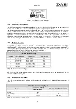
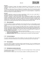
Figure 13: Setting the restart pressure
6.5.6
AD: Address configuration
This is only applicable on multi-inverter systems. It sets the communication address to be assigned to the
inverter. The possible values are: automatic (default), or manually assigned address.
The manually assigned addresses can have values from 1 to 8. Configuration of the addresses must be
uniform for all inverters in the series: either all automatic or all manual. Identical addresses are not admitted.
If the address assignment modes are mixed (some manual and some automatic), and also if an address is
duplicated, the relative error is shown. The error is indicated with a flashing “E” in place of the unit address.
If selected assignment is automatic, each time the system is turned on, the addresses are assigned
automatically and may be different from the previous time; this has no effect on correct operation.
6.5.7
PR: Pressure sensor
Setting of the type of pressure sensor used. This parameter enables selection of a ratiometric or current type
pressure sensor. For each type of sensor, different full scales can be selected. When a ratiometric sensor is
selected (default) the input Press 1 must be used for connection. When a 4-20mA current sensor is used, the
relative screw terminals on the input terminal board must be used.
(See Collegamento del sensore di pressione par 2.2.3.1)
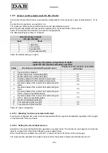
Pressure sensor settings
PR value
Type of sensor
Information
Full scale [bar]
0
Ratiometric
501 R 16 bar
16
1
Ratiometric
501 R 25 bar
25
2
Ratiometric
501 R 40 bar
40
3
4-20 mA
4/20 mA 16 bar
16
4
4-20 mA
4/20 mA 25 bar
25
5
4-20 mA
4/20 mA 40 bar
40
Table 16: Pressure sensor settings
NOTE:
The setting of the pressure sensor does not depend on the pressure to be obtained, but on the
sensor to be fitted on the system.
6.5.8
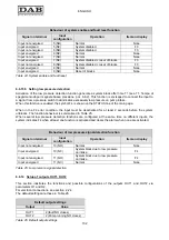
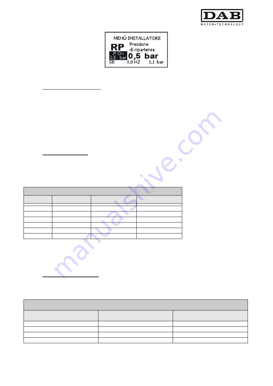
MS: Measurement system
This sets the measurement unit system; either international or Imperial The values displayed are shown in
Table 17.
Units of measurement displayed
Value
International unit of
measurement
Imperial unit of measurement
Restart bar
Temperature °C
°F
Flow
l / min
gal / min
Table 17: Unit of measurement system
Содержание MCE-22/P
Страница 278: ...274 1 276 2 279 3 280 4 282 5 283 6 4 20 284 7 285 8 286 9 287 10 290 11 290 12 292...
Страница 279: ...275 IEC 60634...
Страница 280: ...276 1 6 MCE 22 P MCE 15 P MCE 11 P 1 1 1...
Страница 282: ...278 2 5 2 1 2 1 2 2 1 1 2 1 2 L L L 2 2 4 15...
Страница 283: ...279 2 2 2 1 2 2 1 1 3 1 LN 2 2 3 1 3 4 4...
Страница 284: ...280 A 3 3 2 2 1 2 4 3 1 UVW 2 2 4 3 50 60 200 1...
Страница 286: ...282 4 2 2 3 Press e Flow 5 A B C D d1 d2...
Страница 288: ...284 DIN 43650 6 4 20 2 2 3 2 Flow 6 DIN 43650 6 DIN 43650 2 2 4 4 2 7 8 6 6 13 6 6 14 19 11 18 J5 18 50 A B C D...
Страница 291: ...287 3 9 64 X 128 4 MODE SET 9 7 MODE 1 SET 8 3 EEprom SET 6 SET MODE...
Страница 292: ...288 3 1 9 3 2 1 2 3 2 1 MODE SET MODE 8 2 2 5 5 5 2 2 9...
Страница 294: ...290 3 2 2 10 SET 10 15 12 11...
Страница 295: ...291 3 3 10 11 GO SB BL LP HP EC OC OF SC OT OB BP NC F1 F3 F4 P1 1 P2 2 P3 3 P4 4 E0 E16 0 16 EE EEprom WARN...
Страница 296: ...292 12 12 12 GO SB...
Страница 297: ...293 4 4 1 Link 8 4 2 4 2 1 Link 2 Link 5...
Страница 300: ...296 4 3 1 2 1 4 3 1 3 SET MODE LA RC FN MS FS FL AC AE O1 1 O2 2 4 4 ET 6 6 9 FL...
Страница 302: ...298 5 5 1 2 EC A 8 2 RC 5 1 1 EC MODE SET RC 16 0 A RC SET MODE RC 5 1 2 RC 5 1 1 MODE FN 50 RC FN OC OF BL RC FN...
Страница 305: ...301 6 6 1 MODE MODE 6 1 1 FR 6 1 2 VP 6 1 3 C1 A C1 RC 6 5 1 6 1 4 PO PO 6 1 5 SM 13 SB F 14 SM...
Страница 306: ...302 13 F Sb RC A SM 6 1 6 VE 6 2 2 SET MODE 6 2 1 VF 6 2 2 TE 6 2 3 BT 6 2 4 FF FF x y x y x 1 x y 64 RF 6 2 5 CT...
Страница 312: ...308 6 5 9 FI 17 0 1 F3 00 2 F3 00 3 4 18 6 5 9 1 FK FD 2 FZ 6 5 12 FZ FZ 2 6 6 3 FZ 1 FZ 6 5 5 2 FZ FZ 1 FZ 2 FZ...
Страница 324: ...320 7 BL OC OF SC PD FA 28 BL BP LP HP OT OB OC OF SC EC RC Ei i Vi i 29 7 1 7 1 1 BL TB BL 2 3...
Страница 325: ...321 7 1 2 BP BP 7 1 3 LP 295 348 7 1 4 HP 7 1 5 SC U V W PUMP 10 7 2 7 3 BL LP HP OT OB OC OF BP 29...
Страница 326: ...322 BL 10 6 24 24 30 LP 180 200 HP OT TE 100 C 85 C OB BT 120 C 100 C OC 10 6 OF 10 6 30...
Страница 327: ...323 8 8 1 PMW 4 2 8 2 8 3 8 3 SET EE EEprom FLASH...
Страница 494: ...490 1 492 2 495 3 496 4 498 5 499 6 4 20 mA 500 7 501 8 502 9 503 10 506 11 506 12 508 13 523...
Страница 495: ...491 IEC 364 inverter...
Страница 496: ...492 1 Inverter inverter inverter 6 inverter MCE 22 P MCE 15 P MCE 11 P 1 1 1...
Страница 499: ...495 2 2 2 1 inverter inverter 2 2 1 1 inverter 3 1 LN 2 inverter 2 PVC 3 inverter 1 3 inverter...
Страница 500: ...496 4 4 inverter A 3 3 2 2 1 2 inverter 4 3 1 UVW 2 3 PVC 4 3 inverter inverter 50 Hz 60 Hz 200 Hz inverter 1...
Страница 502: ...498 4 2 2 3 Press Flow 5 A B C D d1 d2...
Страница 507: ...503 3 9 oled 64 X 128 4 MODE SET 9 inverter 7 MODE 1 SET 8 3 EEprom SET 6 SET MODE...
Страница 508: ...504 3 1 9 3 2 1 2 3 2 1 MODE SET Setpoint MODE 9 ONOMA TOY MENOY 2 Setpoint 2 5 5 5 2 2 9...
Страница 512: ...508 12 12 12 GO SB FAULT...
Страница 539: ...535 6 6 14 1 O1 1 1 1 26 6 6 14 2 O2 2 2 2 26 OUT1 OUT2 0 NC NC 1 NC NC 2 NC NC 3 NC NC 27 6 6 15 RF 2 RF 64 FF...
Страница 540: ...536 7 inverter inverter L C F SC PD FA 28 BL BP LP HP OT OB OC OF SC EC RC Ei i Vi i 29 7 1 7 1 1 L setpoint L 2 3...
Страница 542: ...538 BL 10 6 24 24 30 LP 180VAC 200VAC HP OT TE 100 C 85 OB BT 120 C 100 C OC 10 6 24 24 30 OF 10 6 24 24 30 30...
Страница 543: ...539 8 8 1 PMW 4 2 8 2 inverter 8 3 8 3 inverter SET EEPROM FLASH setpoint...
Страница 599: ...595...


