


ENGLISH
105
7.1.2
“BP” Block due to fault on pressure sensor
If the inverter detects a fault on the pressure sensor, the pump remains blocked and the error signal “BP” is
displayed. This status starts as soon as the problem is detected and is reset automatically when the correct
conditions are restored.
7.1.3
"LP" Block due to low power supply voltage
This occurs when the voltage on the line to the power supply terminal falls below 295 Vac. Reset is only
automatic when the voltage to the terminal exceeds 348 Vac.
7.1.4
"HP" Block due to high internal power supply voltage
This occurs when the internal power supply voltage has values outside the specified range. Reset is only
automatic when the voltage returns to within admissible values. This may be caused by changes in power
supply voltage or excessively sudden pump shutdown.
7.1.5
"SC" Block due to direct short circuit between the phases on the output terminal
The inverter is equipped with a protection against direct short circuits, which may occur between the phases
U, V, and W of the output terminal "PUMP". When this block signal is sent, the user can attempt reset by
pressing b and – simultaneously
which in any event does not have any effect until 10 seconds
has passed since the moment of the short circuit.
7.2 Manual reset of error conditions
In error status, the user can reset the fault by overriding a new attempt by pressing and releasing b
and -.
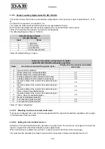
7.3 Auto-reset of error conditions
In the cases of some malfunctions and block conditions, the system makes a number of attempts at
automatic reset of the electric pump.
The auto-reset system regards in particular:
-
"BL"
Block due to water failure
-
"LP"
Block due to low power supply voltage
-
"HP"
Block due to internal high voltage
-
"OT"
Block due to overheating of final power stages
-
"OB"
Block due to overheating of printed circuit
-
"OC"
Block due to current overload on electric pump motor
-
"OF"
Block due to current overload on final stages of output
-
"BP"
Block due to fault on pressure sensor
If, for example, the pump is blocked due to water supply failure, the inverter automatically starts a test
procedure to verify that the unit is effectively without water permanently. During the sequence of operations,
if a reset attempt succeeds (for example water has returned), the procedure is interrupted and normal
operation is resumed.
Table 30 shows the sequence of operations performed by the inverter for the different types of block.
Содержание MCE-22/P
Страница 278: ...274 1 276 2 279 3 280 4 282 5 283 6 4 20 284 7 285 8 286 9 287 10 290 11 290 12 292...
Страница 279: ...275 IEC 60634...
Страница 280: ...276 1 6 MCE 22 P MCE 15 P MCE 11 P 1 1 1...
Страница 282: ...278 2 5 2 1 2 1 2 2 1 1 2 1 2 L L L 2 2 4 15...
Страница 283: ...279 2 2 2 1 2 2 1 1 3 1 LN 2 2 3 1 3 4 4...
Страница 284: ...280 A 3 3 2 2 1 2 4 3 1 UVW 2 2 4 3 50 60 200 1...
Страница 286: ...282 4 2 2 3 Press e Flow 5 A B C D d1 d2...
Страница 288: ...284 DIN 43650 6 4 20 2 2 3 2 Flow 6 DIN 43650 6 DIN 43650 2 2 4 4 2 7 8 6 6 13 6 6 14 19 11 18 J5 18 50 A B C D...
Страница 291: ...287 3 9 64 X 128 4 MODE SET 9 7 MODE 1 SET 8 3 EEprom SET 6 SET MODE...
Страница 292: ...288 3 1 9 3 2 1 2 3 2 1 MODE SET MODE 8 2 2 5 5 5 2 2 9...
Страница 294: ...290 3 2 2 10 SET 10 15 12 11...
Страница 295: ...291 3 3 10 11 GO SB BL LP HP EC OC OF SC OT OB BP NC F1 F3 F4 P1 1 P2 2 P3 3 P4 4 E0 E16 0 16 EE EEprom WARN...
Страница 296: ...292 12 12 12 GO SB...
Страница 297: ...293 4 4 1 Link 8 4 2 4 2 1 Link 2 Link 5...
Страница 300: ...296 4 3 1 2 1 4 3 1 3 SET MODE LA RC FN MS FS FL AC AE O1 1 O2 2 4 4 ET 6 6 9 FL...
Страница 302: ...298 5 5 1 2 EC A 8 2 RC 5 1 1 EC MODE SET RC 16 0 A RC SET MODE RC 5 1 2 RC 5 1 1 MODE FN 50 RC FN OC OF BL RC FN...
Страница 305: ...301 6 6 1 MODE MODE 6 1 1 FR 6 1 2 VP 6 1 3 C1 A C1 RC 6 5 1 6 1 4 PO PO 6 1 5 SM 13 SB F 14 SM...
Страница 306: ...302 13 F Sb RC A SM 6 1 6 VE 6 2 2 SET MODE 6 2 1 VF 6 2 2 TE 6 2 3 BT 6 2 4 FF FF x y x y x 1 x y 64 RF 6 2 5 CT...
Страница 312: ...308 6 5 9 FI 17 0 1 F3 00 2 F3 00 3 4 18 6 5 9 1 FK FD 2 FZ 6 5 12 FZ FZ 2 6 6 3 FZ 1 FZ 6 5 5 2 FZ FZ 1 FZ 2 FZ...
Страница 324: ...320 7 BL OC OF SC PD FA 28 BL BP LP HP OT OB OC OF SC EC RC Ei i Vi i 29 7 1 7 1 1 BL TB BL 2 3...
Страница 325: ...321 7 1 2 BP BP 7 1 3 LP 295 348 7 1 4 HP 7 1 5 SC U V W PUMP 10 7 2 7 3 BL LP HP OT OB OC OF BP 29...
Страница 326: ...322 BL 10 6 24 24 30 LP 180 200 HP OT TE 100 C 85 C OB BT 120 C 100 C OC 10 6 OF 10 6 30...
Страница 327: ...323 8 8 1 PMW 4 2 8 2 8 3 8 3 SET EE EEprom FLASH...
Страница 494: ...490 1 492 2 495 3 496 4 498 5 499 6 4 20 mA 500 7 501 8 502 9 503 10 506 11 506 12 508 13 523...
Страница 495: ...491 IEC 364 inverter...
Страница 496: ...492 1 Inverter inverter inverter 6 inverter MCE 22 P MCE 15 P MCE 11 P 1 1 1...
Страница 499: ...495 2 2 2 1 inverter inverter 2 2 1 1 inverter 3 1 LN 2 inverter 2 PVC 3 inverter 1 3 inverter...
Страница 500: ...496 4 4 inverter A 3 3 2 2 1 2 inverter 4 3 1 UVW 2 3 PVC 4 3 inverter inverter 50 Hz 60 Hz 200 Hz inverter 1...
Страница 502: ...498 4 2 2 3 Press Flow 5 A B C D d1 d2...
Страница 507: ...503 3 9 oled 64 X 128 4 MODE SET 9 inverter 7 MODE 1 SET 8 3 EEprom SET 6 SET MODE...
Страница 508: ...504 3 1 9 3 2 1 2 3 2 1 MODE SET Setpoint MODE 9 ONOMA TOY MENOY 2 Setpoint 2 5 5 5 2 2 9...
Страница 512: ...508 12 12 12 GO SB FAULT...
Страница 539: ...535 6 6 14 1 O1 1 1 1 26 6 6 14 2 O2 2 2 2 26 OUT1 OUT2 0 NC NC 1 NC NC 2 NC NC 3 NC NC 27 6 6 15 RF 2 RF 64 FF...
Страница 540: ...536 7 inverter inverter L C F SC PD FA 28 BL BP LP HP OT OB OC OF SC EC RC Ei i Vi i 29 7 1 7 1 1 L setpoint L 2 3...
Страница 542: ...538 BL 10 6 24 24 30 LP 180VAC 200VAC HP OT TE 100 C 85 OB BT 120 C 100 C OC 10 6 24 24 30 OF 10 6 24 24 30 30...
Страница 543: ...539 8 8 1 PMW 4 2 8 2 inverter 8 3 8 3 inverter SET EEPROM FLASH setpoint...
Страница 599: ...595...


