


ENGLISH
100
6.6.13 Setup of auxiliary digital inputs IN1, IN2, IN3, IN4
This section shows the functions and possible configurations of the inputs by means of parameters I1, I2, I3,
I4.
For electrical connections, see section 2.2.4.
The inputs are all the same and all functions can be associated with each.
Each function associated with the inputs is explained in more detail further in this section.
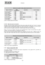
Table 21 summarises the functions and various configurations.
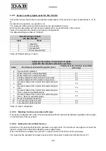
The default settings are those in Table 20.
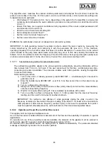
Default settings of inputs
IN1, IN2, IN3, IN4
Input
Value
1
1 (float NO)
2
3 (P aux NO)
3
5 (enable NO)
4
10 (low pressure NO)
Table 20: Default settings of inputs
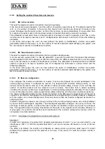
Summary of possible configurations of digital
inputs IN1, IN2, IN3, IN4 and relative operation
Value
Function associated with general input i
Display of active function associated
with input
0
Input functions disabled
1
Water failure from external float (NO)
F1
2
Water failure from external float (NC)
F1
3
Auxiliary setpoint Pi (NO) related to input used
F2
4
Auxiliary setpoint Pi (NC) related to input used
F2
5
General enable of the inverter from external signal
(NO)
F3
6
General enable of the inverter from external signal
(NC)
F3
7
General enable of the inverter from external signal
(NO) + Reset of resettable blocks
F3
8
General enable of the inverter from external signal
(NC) + Reset of resettable blocks
F3
9
Reset of resettable blocks NO
10
Low pressure signal input NO
F4
11
Low pressure signal input NC
F4
Table 21: Input configuration
6.6.13.1 Disabling functions associated with input
If an input is configured at 0, each function associated with this input will be disabled, regardless of the signal
on the terminals of the input itself.
6.6.13.2 Setting the external float function
Activation of the external float function generates a system block. The function is envisaged to connect the
input to a signal from a float that indicates a water supply failure.
When this function is enabled, the symbol F1 is shown on the STATUS line of the main page.
The input must be activated for at least one second for the system to block and indicate the error F1.
Содержание MCE-22/P
Страница 278: ...274 1 276 2 279 3 280 4 282 5 283 6 4 20 284 7 285 8 286 9 287 10 290 11 290 12 292...
Страница 279: ...275 IEC 60634...
Страница 280: ...276 1 6 MCE 22 P MCE 15 P MCE 11 P 1 1 1...
Страница 282: ...278 2 5 2 1 2 1 2 2 1 1 2 1 2 L L L 2 2 4 15...
Страница 283: ...279 2 2 2 1 2 2 1 1 3 1 LN 2 2 3 1 3 4 4...
Страница 284: ...280 A 3 3 2 2 1 2 4 3 1 UVW 2 2 4 3 50 60 200 1...
Страница 286: ...282 4 2 2 3 Press e Flow 5 A B C D d1 d2...
Страница 288: ...284 DIN 43650 6 4 20 2 2 3 2 Flow 6 DIN 43650 6 DIN 43650 2 2 4 4 2 7 8 6 6 13 6 6 14 19 11 18 J5 18 50 A B C D...
Страница 291: ...287 3 9 64 X 128 4 MODE SET 9 7 MODE 1 SET 8 3 EEprom SET 6 SET MODE...
Страница 292: ...288 3 1 9 3 2 1 2 3 2 1 MODE SET MODE 8 2 2 5 5 5 2 2 9...
Страница 294: ...290 3 2 2 10 SET 10 15 12 11...
Страница 295: ...291 3 3 10 11 GO SB BL LP HP EC OC OF SC OT OB BP NC F1 F3 F4 P1 1 P2 2 P3 3 P4 4 E0 E16 0 16 EE EEprom WARN...
Страница 296: ...292 12 12 12 GO SB...
Страница 297: ...293 4 4 1 Link 8 4 2 4 2 1 Link 2 Link 5...
Страница 300: ...296 4 3 1 2 1 4 3 1 3 SET MODE LA RC FN MS FS FL AC AE O1 1 O2 2 4 4 ET 6 6 9 FL...
Страница 302: ...298 5 5 1 2 EC A 8 2 RC 5 1 1 EC MODE SET RC 16 0 A RC SET MODE RC 5 1 2 RC 5 1 1 MODE FN 50 RC FN OC OF BL RC FN...
Страница 305: ...301 6 6 1 MODE MODE 6 1 1 FR 6 1 2 VP 6 1 3 C1 A C1 RC 6 5 1 6 1 4 PO PO 6 1 5 SM 13 SB F 14 SM...
Страница 306: ...302 13 F Sb RC A SM 6 1 6 VE 6 2 2 SET MODE 6 2 1 VF 6 2 2 TE 6 2 3 BT 6 2 4 FF FF x y x y x 1 x y 64 RF 6 2 5 CT...
Страница 312: ...308 6 5 9 FI 17 0 1 F3 00 2 F3 00 3 4 18 6 5 9 1 FK FD 2 FZ 6 5 12 FZ FZ 2 6 6 3 FZ 1 FZ 6 5 5 2 FZ FZ 1 FZ 2 FZ...
Страница 324: ...320 7 BL OC OF SC PD FA 28 BL BP LP HP OT OB OC OF SC EC RC Ei i Vi i 29 7 1 7 1 1 BL TB BL 2 3...
Страница 325: ...321 7 1 2 BP BP 7 1 3 LP 295 348 7 1 4 HP 7 1 5 SC U V W PUMP 10 7 2 7 3 BL LP HP OT OB OC OF BP 29...
Страница 326: ...322 BL 10 6 24 24 30 LP 180 200 HP OT TE 100 C 85 C OB BT 120 C 100 C OC 10 6 OF 10 6 30...
Страница 327: ...323 8 8 1 PMW 4 2 8 2 8 3 8 3 SET EE EEprom FLASH...
Страница 494: ...490 1 492 2 495 3 496 4 498 5 499 6 4 20 mA 500 7 501 8 502 9 503 10 506 11 506 12 508 13 523...
Страница 495: ...491 IEC 364 inverter...
Страница 496: ...492 1 Inverter inverter inverter 6 inverter MCE 22 P MCE 15 P MCE 11 P 1 1 1...
Страница 499: ...495 2 2 2 1 inverter inverter 2 2 1 1 inverter 3 1 LN 2 inverter 2 PVC 3 inverter 1 3 inverter...
Страница 500: ...496 4 4 inverter A 3 3 2 2 1 2 inverter 4 3 1 UVW 2 3 PVC 4 3 inverter inverter 50 Hz 60 Hz 200 Hz inverter 1...
Страница 502: ...498 4 2 2 3 Press Flow 5 A B C D d1 d2...
Страница 507: ...503 3 9 oled 64 X 128 4 MODE SET 9 inverter 7 MODE 1 SET 8 3 EEprom SET 6 SET MODE...
Страница 508: ...504 3 1 9 3 2 1 2 3 2 1 MODE SET Setpoint MODE 9 ONOMA TOY MENOY 2 Setpoint 2 5 5 5 2 2 9...
Страница 512: ...508 12 12 12 GO SB FAULT...
Страница 539: ...535 6 6 14 1 O1 1 1 1 26 6 6 14 2 O2 2 2 2 26 OUT1 OUT2 0 NC NC 1 NC NC 2 NC NC 3 NC NC 27 6 6 15 RF 2 RF 64 FF...
Страница 540: ...536 7 inverter inverter L C F SC PD FA 28 BL BP LP HP OT OB OC OF SC EC RC Ei i Vi i 29 7 1 7 1 1 L setpoint L 2 3...
Страница 542: ...538 BL 10 6 24 24 30 LP 180VAC 200VAC HP OT TE 100 C 85 OB BT 120 C 100 C OC 10 6 24 24 30 OF 10 6 24 24 30 30...
Страница 543: ...539 8 8 1 PMW 4 2 8 2 inverter 8 3 8 3 inverter SET EEPROM FLASH setpoint...
Страница 599: ...595...


