ENGLISH
83
5.1.3
Setting the direction of rotation
Once the pump has started up, the user must ensure that the direction of rotation is correct (the direction
is usually indicated by an arrow on the pump casing). To start up the motor and check the direction of
rotation, simply switch on a utility.
From the same menu as RC (MODE SET – "Installer menu") press MODE and scroll through the menus
to RT. In these conditions, b and – enable the user to invert the direction of motor rotation. The
function is also enabled when the motor is running.
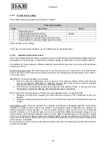
If it is not possible to see the direction of motor rotation, proceed as follows:
Method to check rotation frequency
-
Access parameter RT as described above.
-
Turn on a utility and observe the frequency that is shown on the status bar at the bottom of the utility control
page, to ensure that the operating frequency is less than the rated frequency of the pump FN.
-
Without changing collection, modify parameter RT by means of b or – and check frequency FR again.
-
The correct RT parameter is that which requires, compared to collection, a lower frequency FR.
5.1.4
Setting the flow sensor and pipeline diameter
From the installer menu (the same used to set RC, RT and FN) scroll through the parameters using
MODE to reach FI.
To work without a flow sensor, set FI at 0; to work with the flow sensor set FI at 1. Use MODE to scroll
through to the next parameter FD (pipeline diameter) and set the diameter in inches of the pipeline on
which the flow sensor is mounted.
Press SET to return to the main page.
5.1.5
Setting the setpoint pressure
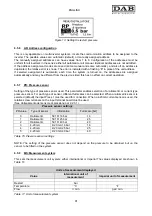
From the main menu, press and hold MODE and SET simultaneously until “SP” appears on display. In
these conditions, buttons “+” and “–“ enable respectively increase and decrease of the required pressure
value.
The regulation range depends on the sensor used.
Press SET to return to the main page.
5.1.6
Setting other parameters
After the initial start-up procedure, the other pre-set parameters can be modified as required, by
accessing the relative menus and following the instructions for the specific parameters (see chapter 6).
The most common parameters are: restart pressure, regulation gain values GI and GP, minimum
frequency FL, water failure time TB, etc.
Содержание MCE-22/P
Страница 278: ...274 1 276 2 279 3 280 4 282 5 283 6 4 20 284 7 285 8 286 9 287 10 290 11 290 12 292...
Страница 279: ...275 IEC 60634...
Страница 280: ...276 1 6 MCE 22 P MCE 15 P MCE 11 P 1 1 1...
Страница 282: ...278 2 5 2 1 2 1 2 2 1 1 2 1 2 L L L 2 2 4 15...
Страница 283: ...279 2 2 2 1 2 2 1 1 3 1 LN 2 2 3 1 3 4 4...
Страница 284: ...280 A 3 3 2 2 1 2 4 3 1 UVW 2 2 4 3 50 60 200 1...
Страница 286: ...282 4 2 2 3 Press e Flow 5 A B C D d1 d2...
Страница 288: ...284 DIN 43650 6 4 20 2 2 3 2 Flow 6 DIN 43650 6 DIN 43650 2 2 4 4 2 7 8 6 6 13 6 6 14 19 11 18 J5 18 50 A B C D...
Страница 291: ...287 3 9 64 X 128 4 MODE SET 9 7 MODE 1 SET 8 3 EEprom SET 6 SET MODE...
Страница 292: ...288 3 1 9 3 2 1 2 3 2 1 MODE SET MODE 8 2 2 5 5 5 2 2 9...
Страница 294: ...290 3 2 2 10 SET 10 15 12 11...
Страница 295: ...291 3 3 10 11 GO SB BL LP HP EC OC OF SC OT OB BP NC F1 F3 F4 P1 1 P2 2 P3 3 P4 4 E0 E16 0 16 EE EEprom WARN...
Страница 296: ...292 12 12 12 GO SB...
Страница 297: ...293 4 4 1 Link 8 4 2 4 2 1 Link 2 Link 5...
Страница 300: ...296 4 3 1 2 1 4 3 1 3 SET MODE LA RC FN MS FS FL AC AE O1 1 O2 2 4 4 ET 6 6 9 FL...
Страница 302: ...298 5 5 1 2 EC A 8 2 RC 5 1 1 EC MODE SET RC 16 0 A RC SET MODE RC 5 1 2 RC 5 1 1 MODE FN 50 RC FN OC OF BL RC FN...
Страница 305: ...301 6 6 1 MODE MODE 6 1 1 FR 6 1 2 VP 6 1 3 C1 A C1 RC 6 5 1 6 1 4 PO PO 6 1 5 SM 13 SB F 14 SM...
Страница 306: ...302 13 F Sb RC A SM 6 1 6 VE 6 2 2 SET MODE 6 2 1 VF 6 2 2 TE 6 2 3 BT 6 2 4 FF FF x y x y x 1 x y 64 RF 6 2 5 CT...
Страница 312: ...308 6 5 9 FI 17 0 1 F3 00 2 F3 00 3 4 18 6 5 9 1 FK FD 2 FZ 6 5 12 FZ FZ 2 6 6 3 FZ 1 FZ 6 5 5 2 FZ FZ 1 FZ 2 FZ...
Страница 324: ...320 7 BL OC OF SC PD FA 28 BL BP LP HP OT OB OC OF SC EC RC Ei i Vi i 29 7 1 7 1 1 BL TB BL 2 3...
Страница 325: ...321 7 1 2 BP BP 7 1 3 LP 295 348 7 1 4 HP 7 1 5 SC U V W PUMP 10 7 2 7 3 BL LP HP OT OB OC OF BP 29...
Страница 326: ...322 BL 10 6 24 24 30 LP 180 200 HP OT TE 100 C 85 C OB BT 120 C 100 C OC 10 6 OF 10 6 30...
Страница 327: ...323 8 8 1 PMW 4 2 8 2 8 3 8 3 SET EE EEprom FLASH...
Страница 494: ...490 1 492 2 495 3 496 4 498 5 499 6 4 20 mA 500 7 501 8 502 9 503 10 506 11 506 12 508 13 523...
Страница 495: ...491 IEC 364 inverter...
Страница 496: ...492 1 Inverter inverter inverter 6 inverter MCE 22 P MCE 15 P MCE 11 P 1 1 1...
Страница 499: ...495 2 2 2 1 inverter inverter 2 2 1 1 inverter 3 1 LN 2 inverter 2 PVC 3 inverter 1 3 inverter...
Страница 500: ...496 4 4 inverter A 3 3 2 2 1 2 inverter 4 3 1 UVW 2 3 PVC 4 3 inverter inverter 50 Hz 60 Hz 200 Hz inverter 1...
Страница 502: ...498 4 2 2 3 Press Flow 5 A B C D d1 d2...
Страница 507: ...503 3 9 oled 64 X 128 4 MODE SET 9 inverter 7 MODE 1 SET 8 3 EEprom SET 6 SET MODE...
Страница 508: ...504 3 1 9 3 2 1 2 3 2 1 MODE SET Setpoint MODE 9 ONOMA TOY MENOY 2 Setpoint 2 5 5 5 2 2 9...
Страница 512: ...508 12 12 12 GO SB FAULT...
Страница 539: ...535 6 6 14 1 O1 1 1 1 26 6 6 14 2 O2 2 2 2 26 OUT1 OUT2 0 NC NC 1 NC NC 2 NC NC 3 NC NC 27 6 6 15 RF 2 RF 64 FF...
Страница 540: ...536 7 inverter inverter L C F SC PD FA 28 BL BP LP HP OT OB OC OF SC EC RC Ei i Vi i 29 7 1 7 1 1 L setpoint L 2 3...
Страница 542: ...538 BL 10 6 24 24 30 LP 180VAC 200VAC HP OT TE 100 C 85 OB BT 120 C 100 C OC 10 6 24 24 30 OF 10 6 24 24 30 30...
Страница 543: ...539 8 8 1 PMW 4 2 8 2 inverter 8 3 8 3 inverter SET EEPROM FLASH setpoint...
Страница 599: ...595...


