ENGLISH
104
7 PROTECTION SYSTEMS
The inverter is equipped with protection systems designed to preserve the pump, motor, power line and the
inverter itself. When one or more protections trip, the one with the highest priority is shown on display.
Depending on the type of error, the electric pump may shut down, but when normal conditions are restored,
the error state may clear automatically, immediately or after a set time interval following automatic reset.
In the case of a block due to water supply failure (BL), block due to pump motor current overload (OC), block
due to final output stage current overload (OF), block due to direct short circuit between the phases on the
output terminal (SC), the user can attempt to manually reset the error condition by pressing and releasing
b and - simultaneously. If the error condition persists, the cause of the fault must be located and
eliminated.
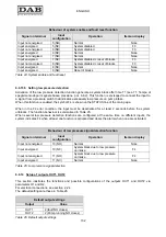
Alarm in fault log
Display message
Description
PD Irregular
shutdown
FA
Problems with cooling system
Table 28: Alarms
Block conditions
Display message
Description
BL
Block due to water failure
BP
Block due to pressure sensor reading error
LP
Block due to low power supply voltage
HP
Block due to high internal power supply voltage
OT
Block due to overheating of final power stages
OB
Block due to overheating of printed circuit
OC
Block due to current overload on electric pump motor
OF
Block due to current overload on final stages of output
SC
Block due to direct short circuit between the phases on the output terminal
EC
Block due to lack of rated current setting (RC)
Ei
Block due to “i” internal error
Vi
Block due to “I” internal voltage outside tolerance
Table 29: Block information
7.1 Description of blocks
7.1.1
“BL” Block due to water failure
In flow conditions below minimum value, with pressure lower than the set regulation value, a water failure
signal is emitted and the system shuts down the pump. The delay interval without pressure and flow can be
set in the parameter TB of the TECHNICAL ASSISTANCE menu.
If the user inadvertently enters a pressure setpoint higher than the pressure that the electric pump can
supply on closure, the system indicates “block due to water failure” (BL) even if this is not precisely the
problem. In this case, lower the regulation pressure to a reasonable value, which does not normally exceed
2/3 of the head of the electrical pump installed.
Содержание MCE-22/P
Страница 278: ...274 1 276 2 279 3 280 4 282 5 283 6 4 20 284 7 285 8 286 9 287 10 290 11 290 12 292...
Страница 279: ...275 IEC 60634...
Страница 280: ...276 1 6 MCE 22 P MCE 15 P MCE 11 P 1 1 1...
Страница 282: ...278 2 5 2 1 2 1 2 2 1 1 2 1 2 L L L 2 2 4 15...
Страница 283: ...279 2 2 2 1 2 2 1 1 3 1 LN 2 2 3 1 3 4 4...
Страница 284: ...280 A 3 3 2 2 1 2 4 3 1 UVW 2 2 4 3 50 60 200 1...
Страница 286: ...282 4 2 2 3 Press e Flow 5 A B C D d1 d2...
Страница 288: ...284 DIN 43650 6 4 20 2 2 3 2 Flow 6 DIN 43650 6 DIN 43650 2 2 4 4 2 7 8 6 6 13 6 6 14 19 11 18 J5 18 50 A B C D...
Страница 291: ...287 3 9 64 X 128 4 MODE SET 9 7 MODE 1 SET 8 3 EEprom SET 6 SET MODE...
Страница 292: ...288 3 1 9 3 2 1 2 3 2 1 MODE SET MODE 8 2 2 5 5 5 2 2 9...
Страница 294: ...290 3 2 2 10 SET 10 15 12 11...
Страница 295: ...291 3 3 10 11 GO SB BL LP HP EC OC OF SC OT OB BP NC F1 F3 F4 P1 1 P2 2 P3 3 P4 4 E0 E16 0 16 EE EEprom WARN...
Страница 296: ...292 12 12 12 GO SB...
Страница 297: ...293 4 4 1 Link 8 4 2 4 2 1 Link 2 Link 5...
Страница 300: ...296 4 3 1 2 1 4 3 1 3 SET MODE LA RC FN MS FS FL AC AE O1 1 O2 2 4 4 ET 6 6 9 FL...
Страница 302: ...298 5 5 1 2 EC A 8 2 RC 5 1 1 EC MODE SET RC 16 0 A RC SET MODE RC 5 1 2 RC 5 1 1 MODE FN 50 RC FN OC OF BL RC FN...
Страница 305: ...301 6 6 1 MODE MODE 6 1 1 FR 6 1 2 VP 6 1 3 C1 A C1 RC 6 5 1 6 1 4 PO PO 6 1 5 SM 13 SB F 14 SM...
Страница 306: ...302 13 F Sb RC A SM 6 1 6 VE 6 2 2 SET MODE 6 2 1 VF 6 2 2 TE 6 2 3 BT 6 2 4 FF FF x y x y x 1 x y 64 RF 6 2 5 CT...
Страница 312: ...308 6 5 9 FI 17 0 1 F3 00 2 F3 00 3 4 18 6 5 9 1 FK FD 2 FZ 6 5 12 FZ FZ 2 6 6 3 FZ 1 FZ 6 5 5 2 FZ FZ 1 FZ 2 FZ...
Страница 324: ...320 7 BL OC OF SC PD FA 28 BL BP LP HP OT OB OC OF SC EC RC Ei i Vi i 29 7 1 7 1 1 BL TB BL 2 3...
Страница 325: ...321 7 1 2 BP BP 7 1 3 LP 295 348 7 1 4 HP 7 1 5 SC U V W PUMP 10 7 2 7 3 BL LP HP OT OB OC OF BP 29...
Страница 326: ...322 BL 10 6 24 24 30 LP 180 200 HP OT TE 100 C 85 C OB BT 120 C 100 C OC 10 6 OF 10 6 30...
Страница 327: ...323 8 8 1 PMW 4 2 8 2 8 3 8 3 SET EE EEprom FLASH...
Страница 494: ...490 1 492 2 495 3 496 4 498 5 499 6 4 20 mA 500 7 501 8 502 9 503 10 506 11 506 12 508 13 523...
Страница 495: ...491 IEC 364 inverter...
Страница 496: ...492 1 Inverter inverter inverter 6 inverter MCE 22 P MCE 15 P MCE 11 P 1 1 1...
Страница 499: ...495 2 2 2 1 inverter inverter 2 2 1 1 inverter 3 1 LN 2 inverter 2 PVC 3 inverter 1 3 inverter...
Страница 500: ...496 4 4 inverter A 3 3 2 2 1 2 inverter 4 3 1 UVW 2 3 PVC 4 3 inverter inverter 50 Hz 60 Hz 200 Hz inverter 1...
Страница 502: ...498 4 2 2 3 Press Flow 5 A B C D d1 d2...
Страница 507: ...503 3 9 oled 64 X 128 4 MODE SET 9 inverter 7 MODE 1 SET 8 3 EEprom SET 6 SET MODE...
Страница 508: ...504 3 1 9 3 2 1 2 3 2 1 MODE SET Setpoint MODE 9 ONOMA TOY MENOY 2 Setpoint 2 5 5 5 2 2 9...
Страница 512: ...508 12 12 12 GO SB FAULT...
Страница 539: ...535 6 6 14 1 O1 1 1 1 26 6 6 14 2 O2 2 2 2 26 OUT1 OUT2 0 NC NC 1 NC NC 2 NC NC 3 NC NC 27 6 6 15 RF 2 RF 64 FF...
Страница 540: ...536 7 inverter inverter L C F SC PD FA 28 BL BP LP HP OT OB OC OF SC EC RC Ei i Vi i 29 7 1 7 1 1 L setpoint L 2 3...
Страница 542: ...538 BL 10 6 24 24 30 LP 180VAC 200VAC HP OT TE 100 C 85 OB BT 120 C 100 C OC 10 6 24 24 30 OF 10 6 24 24 30 30...
Страница 543: ...539 8 8 1 PMW 4 2 8 2 inverter 8 3 8 3 inverter SET EEPROM FLASH setpoint...
Страница 599: ...595...


