3
Scenario 3 – L3 Overlay: 1 WS + 1 AP + 1 Remote AP
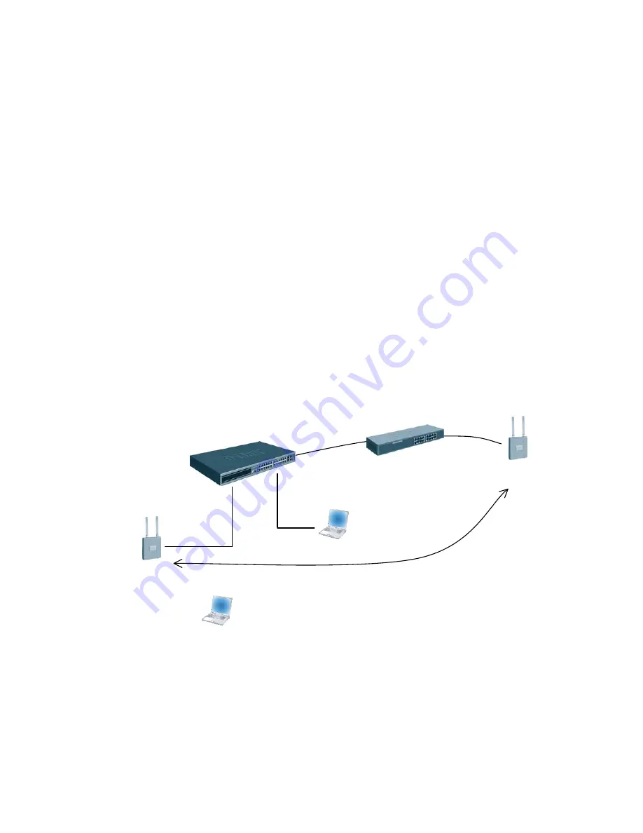
The diagram in this section shows a network configuration with a D-LINK Wireless
Switch connected to an L3 Device/Router. One AP is connected to the D-LINK Wireless
Switch, and the other is connected to the L3 device. Both APs are managed by the D-
LINK Wireless Switch (WS1).
This scenario uses L3 tunneling so that a client that associated with AP1 initiates an
audio conversation and roams to a different subnet. In the process, the client is
disassociated with AP1 and gets associated with AP2 maintaining the audio conversation.
This scenario is especially useful for you to setup a demo in customers’ existing network
with little change to customers’ network configuration.
The objectives for this scenario include the following:
•
To know how to setup the L3 tunneling (L3 Tunneling must be used since the
APs are on different IP subnets and there is not a L2 path between the APs for the
WLAN Network data).
•
To know how to manage the remote AP and the most practical deployment into
customers’ existing networks.
WS1
AP1
Network IP: 10.90.90.90
Loopback: 192.168.10.254
L3 Tunnel: 192.168.250.254
CL1
FTP Server
Audio/Video Server
192.168.20.x
192.168.250.x
SSID:
L3-Tunnel: 192.168.100.x
AP2
L3 Device
Across L3 Network
172.17.5.0/24
172.17.6.0/24
Seamless Roaming
172.17.6.x
In this scenario, the L3 device is part of the customer network. The L3 device must meet
the following minimum requirements:
•
One network to connect to the WS switch (in this scenario, the network is
172.17.5.0/24)
•
One network to connect to AP2 (in this scenario, the network is 172.17.6.0/24)
•
DHCP server in the AP2 network for AP and wireless client addresses
Содержание DWL-3500AP
Страница 12: ...1 6 Save Configuration To save the switch configuration select Save Changes from the tool bar...
Страница 48: ......
Страница 57: ...Then go to Edit and select New Graph and you can input the following then press Save...
Страница 61: ......


