background image

9

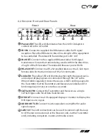
6.2 Receiver Front and Rear Panels

LAN 2

LAN 1

R

L

DVI OUT

AUDIO OUT

POWER

OUT

IN

RS232 

OUT

CAT5e/6/7 

IN

LINK

IR 2

IR 1

1

2

3

4

5

6

7

8

9

Front

Rear

1

  Power LED: The LED will illuminate when the 24 V DC Adaptor is 

connected to the AC outlet.

2

  IR 1 IN: Connect to supplied the IR Receiver cables for IR signal 

reception. Place the IR Blaster in direct line-of-sight of the equipment 

to be controlled. The related IR Transmitter port is IR1 OUT.

3

  IR 2 OUT: Connect to the supplied IR Blaster cables for IR signal 

transmission. Ensure that remote being used is within the direct line-

of-sight of the IR Extender. The related IR Receiver port is IR2 IN. 

4

  RS-232 OUT: Connect to a RS-232 enabled device with a D-Sub 9-pin 

female cable for the transmission of RS-232 commands.

5

  Link LED: The yellow LED will illuminate when both the input source 

and output display signals are connected through the CAT cable. 

When it blinks regularly it states the source is NOT sending a signal to 

the Transmitter but the Transmitter and Receiver are linked and if it 

blink irregularly it states an error has occurred.

6

  CAT5e/6/7 IN: Connect the Transmitter and Receiver via a single 

CAT5e/6 type cable for all data transmission.

7

  DVI OUT: Connect to a DVI equipped display or monitor to display the 

DVI input source signal.

8

  AUDIO OUT L/R: Connect to active speakers or amplifier for audio 

signal output.

9

  LAN 1/2: The LAN connections can be used to connect and share up 

to 4 Ethernet connections (2 at the Receiver end, 2 at the Transmitter 

end), including computers, routers and media servers.

Содержание PU-DVI1109RX

Страница 1: ...PU DVI1109TX RX DVI 5 Play HDBaseT Transmitter and Receiver inc PoC 2x LAN up to 100m OPERATION MANUAL ...

Страница 2: ......

Страница 3: ...rves the right to make improvements to this document and or product at any time and without notice COPYRIGHT NOTICE No part of this document may be reproduced transmitted transcribed stored in a retrieval system or any of its part translated into any language or computer file in any form or by any means electronic mechanical magnetic optical chemical manual or otherwise without express written per...

Страница 4: ...to this product Never push an object of any kind into this product through any openings or empty slots in the unit as you may damage parts inside the unit Do not attach the power supply cabling to building surfaces Use only the supplied power supply unit PSU Do not use the PSU if it is damaged Do not allow anything to rest on the power cabling or allow any weight to be placed upon it or any person...

Страница 5: ... System Requirements 7 5 Features 7 6 Operation Controls and Functions 8 6 1 Transmitter Front and Rear Panels 8 6 2 Receiver Front and Rear Panels 9 6 3 IR Cable Pin Assignment 10 6 4 D Sub 9 Pin Definitions 10 7 Connection Diagram 11 8 Specifications 12 9 Acronyms 13 ...

Страница 6: ... greater flexibility in installations 2 APPLICATIONS Household entertainment media sharing and control Lecture room display and control Showroom display and control Meeting room presentation and control Classroom display and control Any Smart AV Installation system 3 PACKAGE CONTENTS Transmitter Package DVI to CAT5e 6 7 with LAN PoC IR Transmitter 1 IR Blaster 1 IR Receiver 24V DC Power Adaptor Op...

Страница 7: ...ansmitter end 2 at the Receiver end at speeds up to 100Mbps Supports Bi directional IR control and RS 232 pass through Supports 5Play convergence HD video audio Control ports IR and RS232 LAN PoC Installation friendly Single power supply powers both units Receiver unit is powered through the Transmitter via PoC Note 1 This system was tested with CAT6 23AWG cables results may vary with cables of a ...

Страница 8: ...ated IR Transmitter port is IR2 OUT 5 RS 232 IN Connect to a PC Laptop with a D Sub 9 pin male cable for the transmission of RS 232 commands 6 Link LED The yellow LED will illuminate when both the input source and output display signals are connected through the CAT cable When it blinks regularly it states the source is NOT sending a signal to the Transmitter but the Transmitter and Receiver are l...

Страница 9: ...nabled device with a D Sub 9 pin female cable for the transmission of RS 232 commands 5 Link LED The yellow LED will illuminate when both the input source and output display signals are connected through the CAT cable When it blinks regularly it states the source is NOT sending a signal to the Transmitter but the Transmitter and Receiver are linked and if it blink irregularly it states an error ha...

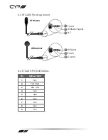
Страница 10: ...Cable Pin Assignment 3 1 2 3 2 1 Power IR Blaster Signal NC IR Signal Power Ground IR Receiver IR Blaster 6 4 D Sub 9 Pin Definitions Pin Define TX RX 1 N C 2 TxD RxD 3 RxD TxD 4 N C 5 GND 6 N C 7 N C 8 N C 9 N C ...

Страница 11: ...DC 24V POWER IN OUT RS232 IN CAT5e 6 7 OUT LINK IR 2 IR 1 IR BLASTER 1 5m 60 IR RECEIVER 7m 3m 3m 60 7m 3m 3m 60 m 1 5m 60 7m 3m 3m 60 m PC Media Server Notebook Monitor Display RS232 Controlled Device Notebook Active Speakers Modem Router TX PC with RS232 Control RX Single CAT5e 6 7 IR Blaster IR Blaster Power Supply IR Extender IR Extender ...

Страница 12: ... Out Supports Resolution 480i 1080p 50 60 1080p 24 VGA WUXGA Dual Link DVI Not Supported IR Frequency 30 50kHz ESD Protection Human body model 8kV air gap discharge 4kV contact discharge Power Supply 24V 1 25A DC US EU Standards CE FCC UL certi fied Dimensions 125mm W x 123mm D x 30mm H Jacks Excluded 125 mm W x 135 mm D x 30 mm H Jacks Included Weight 384g TXC 392g RXC Chassis Material Aluminum S...

Страница 13: ...13 9 ACRONYMS ACRONYM COMPLETE TERM CAT5e Category 5 Cable CAT6 Category 6 Cable CAT7 Category 7 Cable HDMI High Definition Multimedia Interface PoC Power over Cable ...

Страница 14: ......

Страница 15: ......

Страница 16: ...CYP UK Ltd Unit 7 Shepperton Business Park Govett Avenue Shepperton Middlesex TW17 8BA Tel 44 0 20 3137 9180 Fax 44 0 20 3137 6279 Email sales cypeurope com www cypeurope com v1 00 ...

Отзывы: