8
6. OPERATION CONTROLS AND FUNCTIONS
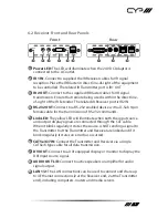
6.1 Transmitter Front and Rear Panels
LAN 2
LAN 1
R
L
DVI IN
AUDIO IN
DC 24V
POWER
IN
OUT
RS232 IN
CAT5e/6/7 OUT
LINK
IR 2
IR 1
1
2
3
4
5
6
7
8
9
10
Front
Rear
1
Power LED: This LED will illuminate when the 24 V DC Adaptor is
connected to the AC outlet.
2
DC 24V: Plug the 24 V DC power supply into the unit and connect the
adaptor to an AC outlet.
3
IR 1 OUT: Connect to the supplied IR Blaster cables for IR signal
transmission. Place the IR Blaster in direct line-ofsight of the
equipment to be controlled. The related IR Receiver port is IR1 IN.
4
IR 2 IN : Connect to the supplied IR Receiver cables for IR signal
reception. Ensure that remote being used is within the direct line-of-
sight of the IR Extender. The related IR Transmitter port is IR2 OUT.
5
RS-232 IN: Connect to a PC/Laptop with a D-Sub 9-pin male cable for
the transmission of RS-232 commands.
6
Link LED: The yellow LED will illuminate when both the input source
and output display signals are connected through the CAT cable.
When it blinks regularly it states the source is NOT sending a signal to
the Transmitter but the Transmitter and Receiver are linked and if it
blink irregularly it states an error has occurred.
7
CAT5e/6/7 OUT: Connect the Transmitter and Receiver via a single
CAT5e/6 type cable for all data transmission.
8
DVI IN: Connect to the DVI equipped source equipment such as PC or
Laptop.
9
AUDIO IN L/R: Connect from audio source equipment for audio signal
output to L/R output on the Receiver side.
10
LAN 1/2: The LAN connections can be used to connect and share up
to 4 Ethernet connections (2 at the Receiver end, 2 at the Transmitter
end), including computers, routers and media servers.


