


AutoView Commander Installer/User Guide
Connecting Computers to the AutoView
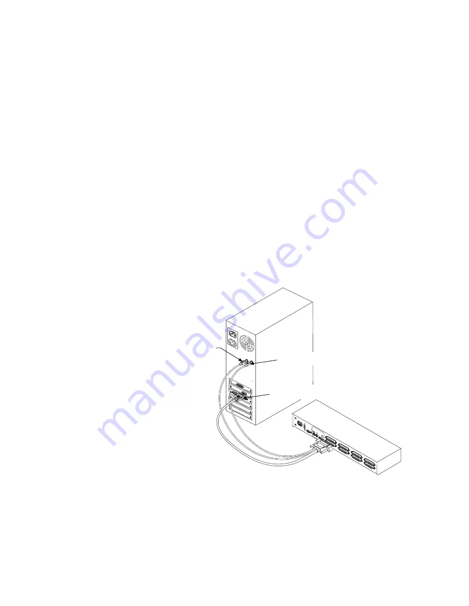
4. Locate your first input cable. It will have a 25-pin “D” connector at one
end. Plug this cable into any lettered channel port on the rear of the
AutoView. The other end of the input cable will have five connectors:
a 15-pin “HDD” connector for your video, a 5-pin DIN/6-pin miniDIN
connector for an AT or PS/2 keyboard connection, and a 9-pin serial/
6-pin miniDIN connector for a serial or PS/2 mouse connection. The
PS/2 mouse connector is designated by a yellow band or mouse icon.
Use only the keyboard and mouse connectors which are
appropriate for your PC, and leave the others unconnected.
Plug these connectors into the matching ports on your computer.
5. Locate your next input cable. Repeat step 4 until all computers are
properly attached to the AutoView.
PO
WER
100-
240V
MADE IN USA
G
H
E
F
C
D
A
B
PA
TEN
T PENDING
T 2
A, 2
50
VA
C
USER
MOUSE PORT
KEYBOARD PORT
VIDEO PORT
6
Содержание AUTOVIEW COMMANDER -
Страница 1: ...Installer User Guide ...
Страница 2: ...AutoView Commander Installer User Guide ...
Страница 10: ...AutoView Commander Installer User Guide ...


