17
2) No matter the Power module is connected to the mains power or not, the
output of the Power module may be electrically live. The parts inside the unit
may still have hazardous voltage after turning off the Power module. To make
the Power module have no output, turn off the Power module, and cut off the
mains power supply, wait the Power module shut down completely, finally cut
off the battery connection.
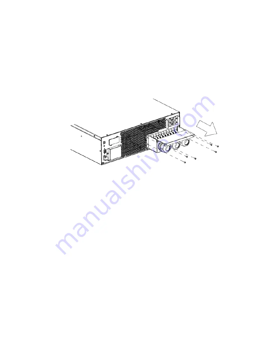
3) Open the terminal block cover located on the rear panel of Power module,
please refer to the appearance diagram.
4) For OLS6000ERT6U(M), it is recommended to select the UL1015
10AWG/6mm² or other insulated wire which complies with AWG Standard for
the Power module input and output wirings.
5) For OLS10000ERT6U(M), it is recommended to select the UL1015
8AWG/10mm² or other insulated wire which complies with AWG Standard for
the Power module input and output wirings.
6) Ensure the capacity of mains power supply. Do not use the wall receptacle as
the input power source for the Power module, as its rated current is less than
the Power module
’s maximum input current. Otherwise the receptacle may be
burned and destroyed.
7) The protective earth ground wire should be installed first according to the
following diagram. It is better to use green wire or green wire with yellow ribbon
wire.
8) Connect other input and output wires to the corresponding input and output
terminals according to the following diagram.
9) Operating procedure for connecting with the Battery module by following the
chapter 6.2.


