I.B. 48008
Page 3
Effective 11/97
the field has not yet been energized by the DC power
supply, or the converse, the motor coasting to a stop with
the field deenergized.
The controller protective functions include:
1.
Locked-rotor protection
2.
Incomplete-sequence protection
3.
Failure-to-synchronize protection
4.
Loss-of-synchronization (pull-out) protection
5.
Open-phase protection
6.
DC loss (field loss) protection
Automatic power factor regulation is not included with the
standard unit, but is available as an option.
Functions
Mark V controllers for synchronous motors consist of the
basic components shown in Figure 4. Their functions are
as follows:
The line contactor (M) operates to connect the motor to
the AC line. Additional contactors are required in reduced-
voltage starters to short out the reactor or to connect and
disconnect the autotransformer in the circuit.
The overload protection relay (e.g., IQ1000-II) protects the
motor from damage by overcurrent conditions, single
phasing, or other abnormal conditions such as phase
reversal or ground fault. It operates to trip the line
contactor M.
The starting and field-discharge resistor (S/D RES) is
used to improve the motor starting torque and to limit the
induced field voltage during starting or when the field
excitation is removed. The resistor current and ohmic
values are determined by the motor designer. The motor
controller is designed to operate motors with less than
1,500 volts rms in the field during starting. The current
flowing to the resistor is controlled by diode D1 and SCR
Q4 (Fig. 4). Voltage feedback (VR on the synchronizing
control board) provides information about the induced field
voltage, frequency, and phase angle.
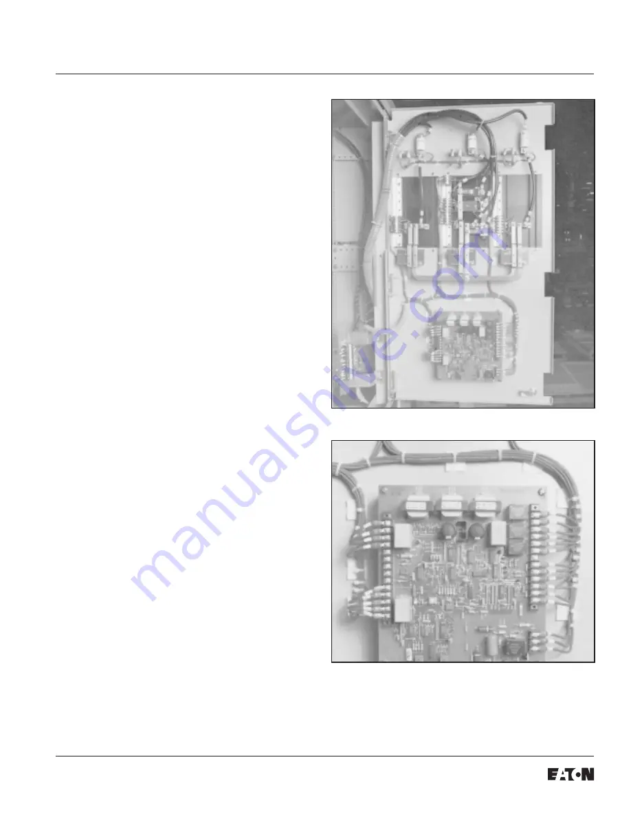
Fig. 2 Mark V Field Power Supply Panel
Fig. 3 Synchronizing Control Board


