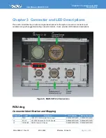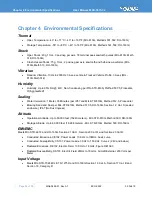
Chapter 3 Connector and LED
Descriptions
User Manual, MAR-5915-3x
Page 34 of 39
MNL-0659-01 Rev A7
ECO-5592
05 Feb 19
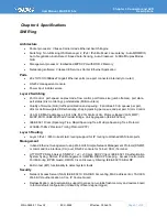
System
Reliability
Workmanship: assembled to IPC-A-610 Class III Workmanship
No moving parts. no active cooling required
Conformal-coated PCBs for humidity/tin-whisker mitigation, staked components, underfilled BGA
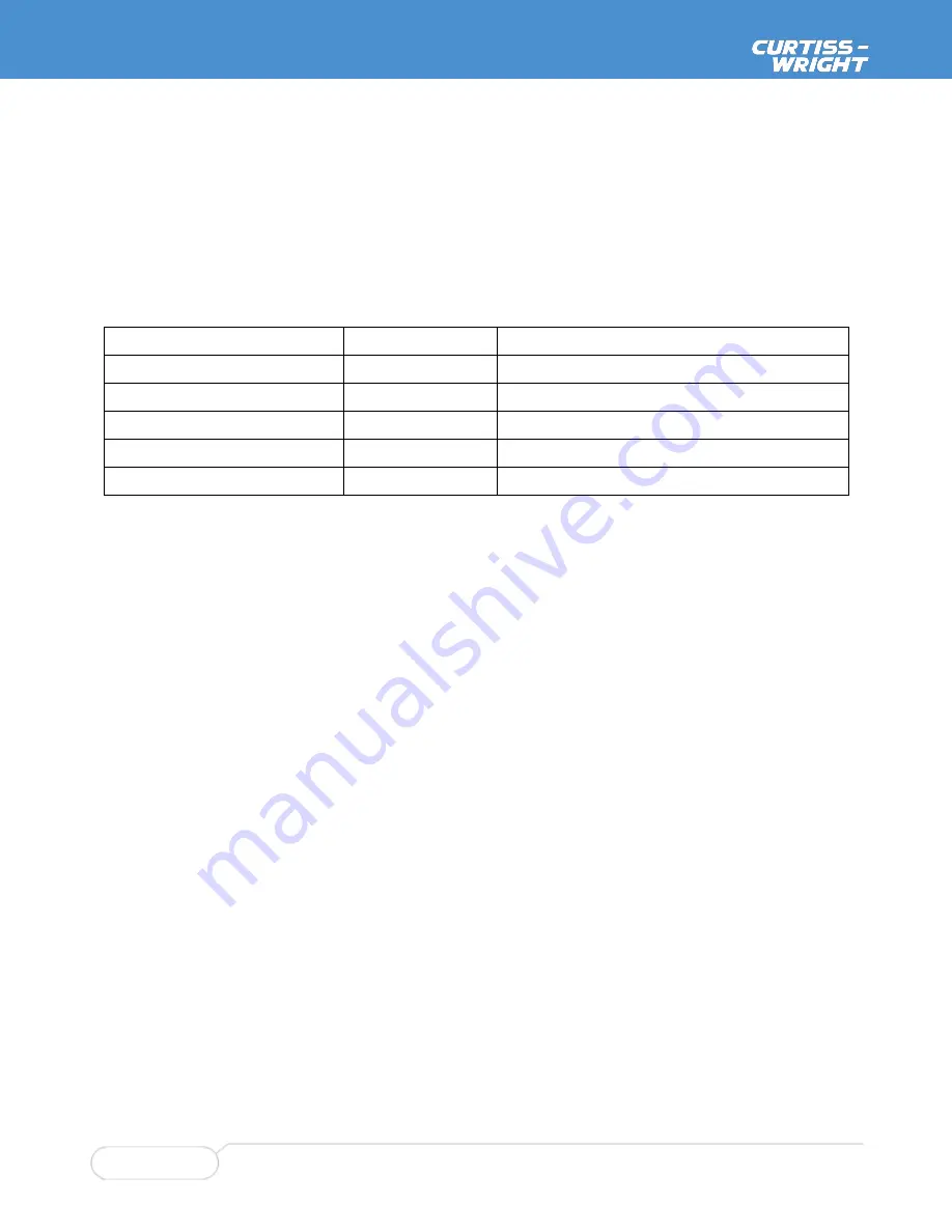
MTBF: Calculated per MIL-HDBK-217F
Environment
Hours ( at 25C)
Hours ( at 40C)
Ground Benign
273,821
207,633
Ground Mobile
21,283
16,038
Airborne Inhabit Fighter
19,951
16,047
Airborne Un-Inhabited Fighter
7,980
6,419
Airborne Rotary Wing
9,363
7,267
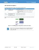
Status Indication
LED Indicators for power (PWR) and link status (LNK)
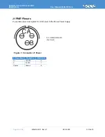
Power
28 VDC nominal input voltage, input range: 9-36 VDC. Operates down to 6v for short durations.
Power Consumption: (Estimated)<35 W Max
Qualified to MIL-STD-704F and MIL-STD-1275D Steady State Voltage, Ripple, Surges, and
Spikes
Non-Isolated

