


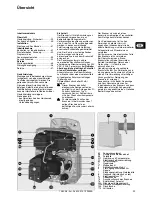


12/2008 - Art. Nr. 4200 1013 9300A
32
Installation
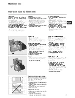
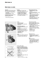
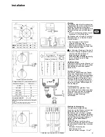
Assembly
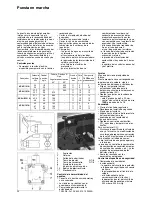
The burner is secured on the boiler with
the flange supplied. Holes are drilled as
shown in the drawing. The flange gasket
can be used as a template.
• Mount the flange and its gasket on the
boiler. Check for leaks.
The burner is installed in position
1
.
If necessary, it may be installed in
position
2
or
3
.
• Insert the connecting nozzle into the
flange (insertion: see boiler manual).
• Tighten the clamp, raising the burner
slightly.
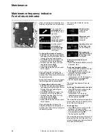
To fit it in position
2
, reverse the
display. To do this while the burner is
operating:
Hold buttons
BP1
and
BP2
down at
the same time, until you notice a
change.
Fuel oil connection
When connecting R 3/8 hoses to the
piping, allow for the burner to be
removed.
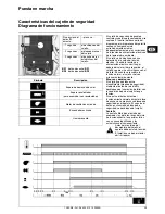
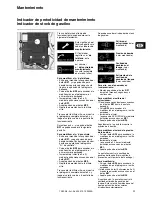
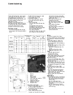
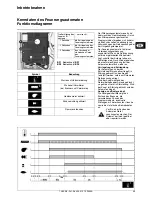
Two-line connection
The illustration opposite allows the
diameter (Ø) and the length (L) of the
piping to be determined from the suction
height (H+) or load (H-) (for fuel oil with
a density of 0.84, to a temperature of
10°C, in an installation which includes
one valve, one non-return valve and four
elbows, at the most).
Single line connection
(for a charged tank only)
Remove the return hose, remove the
connection and the bypass cap. Plug it
using a cylindrical cap and a seal.
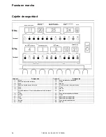
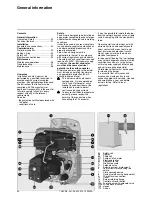
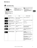
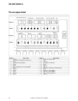
Electrical connection
The electrical setup and the burner
connection must be performed in
compliance with the standards in force.
The burner is supplied with a 7 pin male
connector, to which the single-phase
230V-50Hz power supply with earth and
the thermostat are connected (diagram
opposite).
NB: External connection of an alarm
between S3 and N and an hour meter
between B4 and N.
- Rating of the protective fuse: 6.3A
- Conductor section: 1.5 mm
2
Corrected
H
(m)
L (m)
two-line pump 60 l/h
max
single line
US gal/h
0.60 1.00
Ø 4/6 mm
Ø 6/8 mm Ø 8/10 mm
4
3
2
1
0.5
0
-0.5
-1
-2
-3
17
14
12
10
9
8
7
6
4
-
54
47
40
34
31
27
24
21
14
8
80
70
60
51
46
42
-
-
-
-
48
42
36
30
28
25
-
-
-
-
Correction of altitude
Pump in suction (H +) or charging (H -) mode
Altitude (m)
Theoretical H (m)
0-500
0
501-800
0.5
801-1300
1.0
1301-1800
1.5
1801-2200
2.0
e.g.: altitude 1100m. Theoretical H = 1m actual H 2m.
Corrected H for suction 2 + 1 = 3m
Corrected H for charging 2 - 1 = 1m
Choose the Ø of the piping from the table, based on the
length expanded between the tank and pump.
If corrected H for suction exceeds 4m; make provisions for
a transfer pump (max. pressure 2 bar).
a (mm)
b (mm)
c
d
NC4/6
85-104 150-170
M8
45°
NC9
95-104 150-170
M8
45°
Содержание NC4
Страница 52: ...12 2008 Art Nr 4200 1013 9300A 52 R 1 2 9 BP1 BP1 B 2 BP2 R A4...
Страница 53: ...12 2008 Art Nr 4200 1013 9300A 53 230 1 14 2 15 3 16 4 17 L1 5 18 6 19 7 20 8 21 9 22 10 23 11 24 12 25 13 26...
Страница 54: ...12 2008 Art Nr 4200 1013 9300A 54 K 0 A B...
Страница 55: ...12 2008 Art Nr 4200 1013 9300A 55 BP1 c 400...
Страница 57: ...12 2008 Art Nr 4200 1013 9300A 57...
Страница 58: ...12 2008 Art Nr 4200 1013 9300A 58...
Страница 59: ...12 2008 Art Nr 4200 1013 9300A 59...


