12
GG-6
Configuring the Control Panel
Preparation
The key to accurate and timely programming
is defining the configuration parameters
ahead of time. Included with the control
panel are blank worksheets to fill out prior to
programming.
Since the Actions parameters tie all of the
Sensors, Groups and Relays together, defining
the configuration parameters in the following
order will usually make programming easier to
assimilate.
1. Sensors
2. Groups
3. Relays
4. Actions
Naming
Sensors: Typically, using the sensor location for
the name provides the best information. For
example: Compressor Room, Freezer A, etc.
Groups: Name groups of sensors that share
the same action. For example: North Dock
Sensors, Comp Room Sensors, etc.
Relays: The relay output function typically
works best for the name of the relay. For
example: Exhaust fans, EV12 shutoff, etc.
Actions: Name each action in a way that best
defines its relationship to the sensor/group
and relay output. For example: Any warn = Exh
fans, Alarm = HornStrobe, etc.
Navigating the Menu
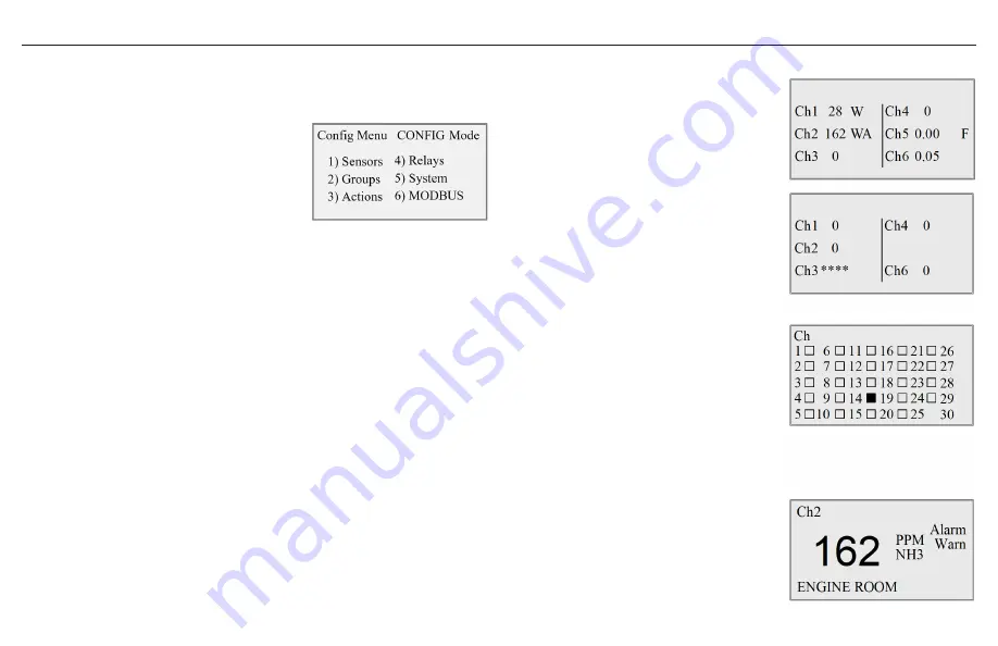
System Display Screen
After system power-up, the normal operating
screen will be displayed. It provides at-a-
glance system status, showing real-time gas
concentrations. The Warn, Alarm and Fault
indications (W, A and F,) will flash until the
conditions are cleared. In this example, Channel
1 gas concentration has exceeded the warn
setpoint. Channel 2 has exceeded the warn and
alarm setpoints. Channel 5 indicates a fault due to
faulty wiring or a sensor signal less than 1 mA. In
the example screen on the right, the absence of
Channel 5 indicates that the sensor has been set
to inactive; therefore the channel is turned off.
Depending on the number of expansion modules
installed, the display changes accordingly. See
Alternate System Display Screens on page 9 for a
detailed description.
PREV or NEXT to go to Channel View screens.
MENU to go to main menu screen.
Channel View
Channel view displays only the status of the
channel being viewed. It also displays the room/
zone location. Warn, Alarm and Fault indications
will flash until the conditions are cleared. PREV
or NEXT to view normal operating screen or next
channel view screen. MENU to go to main menu
screen.
Содержание GG-6
Страница 1: ...Installation and Operation Manual GG 6 MULTI CHANNEL GAS DETECTION CONTROL PANEL ...
Страница 8: ...8 GG 6 ...
Страница 11: ...11 GG 6 Menu Tree ...
Страница 20: ...ctiengineering com 866 394 5861 GG6 DOC2 2 20211103 ...


