Installation manual CHARGESTORM® Connected
page
7
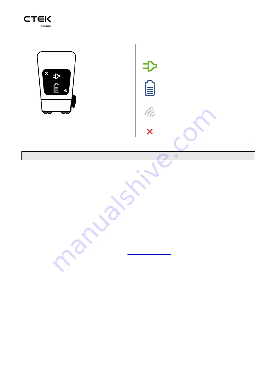
Figure 9 CHARGESTORM® Connected symbols.
Models with double outlets have two rows of
symbols
Display symbols
CHARGESTORM® Connected
available for charging
CHARGESTORM® Connected
in
use. Fixed blue light when connected.
Pulsing blue light when charging.
RFID- Green
–
waiting for tag,
blinking yellow
–
checking tag,
blinking green
–
tag approved,
blinking red - tag denied
Out of order.
6
Provisioning
When the electrical and network installation is ready shall CHARGESTORM® Connected be
configured for operational use (such as network configuration and portal configuration). The Portal
is a software that is used for remote operation and maintenance of CHARGESTORM® Connected. To
configure the CHARGESTORM® Connected control board through the local web interface is a mini
USB cable required. The mini-USB port is located on the control board while a standard USB port is
used on the computer for configuration. If the computer is running Microsoft Windows must an
Ethernet to USB-driver be installed to support access to the local web interface. For Linux and Mac
OSX is the driver part of the operating system. For detailed description of the local web interface
see ref. 1)
CTEK E-Mobility recommends that the installation technician documents the result of the
provisioning tests in a dedicated protocol.
Perform the following step to complete CHARGESTORM® Connected configuration.
1.
Log in to the local web interface. URL:
ccu
and password
ccu.
All modern web browsers work but Chrome is recommended.
2.
Configure network interface (Ethernet or 3G) so that internet access is available
3.
Configure URL and charging station identity (ChargeboxId) to portal
4.
Configure usage of RFID
5.
Configure load balancing
6.1
Local web interface
To connect to the local web interface shall a USB cable be connected between the computer and
CHARGESTORM® Connected controller board mini USB port. In your browser enter IP address


