Installation manual CHARGESTORM® Connected
page
4
5
Installation
Step 1) Unpack CHARGESTORM® Connected
–
Unpack
CHARGESTORM® Connected and all parts from the cardboard
box.
Step 2) Drill holes in the wall
–
Decide mounting position on
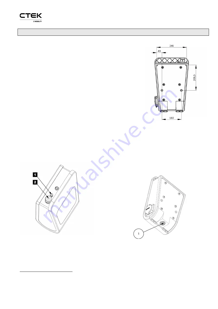
the wall. Drill four holes according to drawing, see Figure 4.
Step 3) Decide input location for power and network
1
–
Power and network cable can either be connected from the top
or the bottom. If cables are inserted from below must holes be
drilled in the unit according to Figure 3. It is strongly advised
that power cable is coming from below for outdoor installation,
avoiding any problems with water entering the unit from the
top along the cable during rain.
When cables are connected from the
top
: There are two holes
on the top. The largest 2. (M32) is for power while the smaller
1. (M12) is for network see Figure 5. The cable gland for 1. that
is delivered with the product supports cable dimensions
between12-22mm while the gland for 2. supports 3-6mm. The glands must be replaced if the cables
are outside specified range. If CHARGESTORM® Connected shall be part of a load balancing
installation or be connected to the backend via Ethernet must a network cable be connected to the
controller board RJ45 port. Cable glands shall be used to protect for dust and water penetration.
More information related to load balancing is available in, ref. 2) and ref. 3). If wiring is connected
from below must holes be drilled in the unit according to Figure 3.
Figure 5 Cable glands for incoming cables
Step 4) Wall mount CHARGESTORM® Connected
–
Unlock and open CHARGESTORM®
Connected with the key. Locate the four screwing holes in the back cover. M8 screw with at least t
1
For three-phase CHARGESTORM® Connected models with dual connectors power cable must
enter from below. Further, these CHARGESTORM® Connected models support 16mm
2
cable area.
Figure 3 Hole distances
Figure 4 Drill location


