123
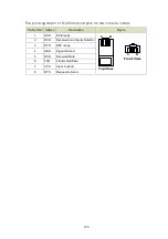
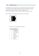
The pin assignment of RJ-45 modular jack on the console cable:
Pin Number Abbrev.
Description
Figure
1
DSR
DCE ready
2
DCD
Received Line Signal Detector
3
DTR
DTE ready
4
GND
Signal Ground
5
RXD
Received Data
6
TXD
Transmitted Data
7
CTS
Clear to Send
8
RTS
Request to Send
1 8
1 8
Top View
Front View
Содержание SHRM03b TDM Series
Страница 1: ...SHRM03b G SHDSL bis TDM Series 4U 19 Chassis ...
Страница 2: ......
Страница 23: ...23 When using 4 wire 2 pairs mode only the upper side of RJ 45 connector can be used ...
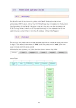
Страница 37: ...37 3 5 1 Menu Tree diagram 2 wire mode ...
Страница 38: ...38 3 5 2 Menu Tree diagram 4 wire mode ...
Страница 52: ...52 75 Ohms 120 Ohms BNC Connector RJ 45 Connector ...
Страница 59: ...59 ...
Страница 78: ...78 ...
Страница 81: ...81 3 8 2 1 E1 interface 2 wire mode 3 8 2 2 E1 interface 4 wire mode 3 8 2 3 Series interface 2 wire mode ...
Страница 82: ...82 3 8 2 4 Series interface 4 wire mode 3 8 2 5 Ethernet interface 2 wire mode ...
Страница 83: ...83 3 8 2 6 Ethernet interface 4 wire mode ...
Страница 84: ...84 3 8 2 7 T1 interface 2 wire mode 3 8 2 8 T1 interface 4 wire mode ...
Страница 86: ...86 3 8 3 3 Ethernet interface For Ethernet interface model ...
Страница 87: ...87 3 8 3 4 T1 interface For T1 interface model ...
Страница 94: ...94 3 12 Exit To exit the console configuration mode cursor down to exit and press Enter Answer y es to confirm ...
Страница 105: ...105 Ethernet Rate Auto Speed Duplex ...
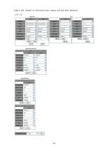
Страница 113: ...113 side Click Reset button and the values will be set to default ...
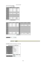
Страница 116: ...116 4 5 7 4 SNMP All SNMP parameter must setup on this item ...
Страница 128: ...128 cable ...
Страница 131: ...131 ...
Страница 136: ...136 ...
Страница 137: ......
Страница 138: ......


