


28
temperature might exceed 45
˚
C.
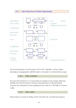
Step 1. Insert the chassis into the 19-inch or 23-inch rack ensuring the
rack-mounting holes on the chassis line up to the mounting hole on the rack.
Step 2. Secure the chassis to the rack with the supplied rack screws. Fasten the
lower pair of screws before the upper pair of screws. This ensures that the
weight of the unit is evenly distributed during installation. Ensure that the
ventilation holes are not obstructed.
It is recommended that the SHRM03b chassis be mounted into the rack
cabinet prior to installing any required power modules and line cards. Without
cards, the chassis is light weight and can easily be installed by a single person.
WARNING:
A fully loaded chassis can be quite heavy and unbalanced.
Dropping a fully loaded chassis would result in severe damage to the chassis
and line cards, as well has pose a serious safety hazard resulting in bodily injury
to the installation personnel. Only trained and qualified personnel should be
allowed to install, replace, or service this equipment.
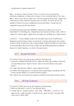
2.3.3
AC power Connection
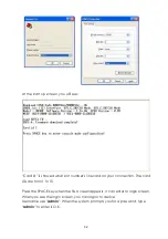
To connect the AC power supply is perform the following:
1. Using the supplied standard power cable with safety grounding connector,
connect the power cable to the AC main socket located on the back
panel.
2. Connect the power cable to a grounded AC outlet.
3. Confirm that the device is connected and operating by checking that the
Power Supply LED(AC) on the front panel is green.
The chassis can use dual power supply modules for redundant power system
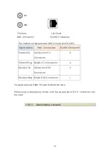
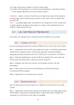
2.3.4
DC Power Connection
To connect the DC power supply is perform the following:
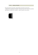
1. Remove the plastic cover on the terminal block.
2. Loosen the two screws marked “-48V” and ”PWR GND”, so that you can
slide the DC cable beneath it. Insert the DC cable into the connector first,
and screw it down tight.
Содержание SHRM03b TDM Series
Страница 1: ...SHRM03b G SHDSL bis TDM Series 4U 19 Chassis ...
Страница 2: ......
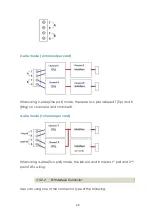
Страница 23: ...23 When using 4 wire 2 pairs mode only the upper side of RJ 45 connector can be used ...
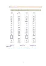
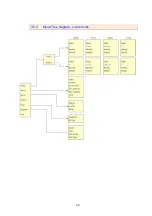
Страница 37: ...37 3 5 1 Menu Tree diagram 2 wire mode ...
Страница 38: ...38 3 5 2 Menu Tree diagram 4 wire mode ...
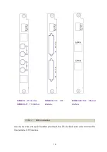
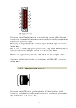
Страница 52: ...52 75 Ohms 120 Ohms BNC Connector RJ 45 Connector ...
Страница 59: ...59 ...
Страница 78: ...78 ...
Страница 81: ...81 3 8 2 1 E1 interface 2 wire mode 3 8 2 2 E1 interface 4 wire mode 3 8 2 3 Series interface 2 wire mode ...
Страница 82: ...82 3 8 2 4 Series interface 4 wire mode 3 8 2 5 Ethernet interface 2 wire mode ...
Страница 83: ...83 3 8 2 6 Ethernet interface 4 wire mode ...
Страница 84: ...84 3 8 2 7 T1 interface 2 wire mode 3 8 2 8 T1 interface 4 wire mode ...
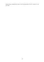
Страница 86: ...86 3 8 3 3 Ethernet interface For Ethernet interface model ...
Страница 87: ...87 3 8 3 4 T1 interface For T1 interface model ...
Страница 94: ...94 3 12 Exit To exit the console configuration mode cursor down to exit and press Enter Answer y es to confirm ...
Страница 105: ...105 Ethernet Rate Auto Speed Duplex ...
Страница 113: ...113 side Click Reset button and the values will be set to default ...
Страница 116: ...116 4 5 7 4 SNMP All SNMP parameter must setup on this item ...
Страница 128: ...128 cable ...
Страница 131: ...131 ...
Страница 136: ...136 ...
Страница 137: ......
Страница 138: ......


