


13
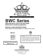
TABLE 7.1: SUMMARY OF HORIZONTAL VENTING OPTIONS
VENT OPTION #
1
2
3
CLASSIFICATION USED IN THIS
MANUAL
HORIZONTAL
CONCENTRIC
HORIZONTAL
TWIN PIPE
HORIZONTAL
CONCENTRIC
ILLUSTRATED IN FIGURE
7.2
7.3
7.2
VENT PIPE PENETRATION
THROUGH STRUCTURE
WALL
WALL
WALL
AIR INTAKE PIPE PENETRATION
THROUGH STRUCTURE
WALL
WALL
WALL
VENT PIPE SIZE
60/100 mm
CONCENTRIC
3”
80/125 mm
CONCENTRIC
AIR INTAKE PIPE SIZE
3”
MAXIMUM LENGTH
VENT
BWC070
32ft
100ft
100ft
BWC090
32ft
100ft
100ft
BWC120
18ft
100ft
100ft
BWC151
100ft
100ft
INLET
BWC070
32ft
100ft
100ft
BWC090
32ft
100ft
100ft
BWC120
18ft
100ft
100ft
BWC151
100ft
100ft
MINIMUM LENGTH
VENT
BWC070
10in
10in
10in
BWC090
10in
10in
10in
BWC120
10in
10in
10in
BWC151
10in
10in
INLET
BWC070
10in
10in
10in
BWC090
10in
10in
10in
BWC120
10in
10in
10in
BWC151
10in
10in
VENT TERMINAL
60/100 mm
CONCENTRIC
CROWN
#230511
Crown 230531
CONCENTRIC
or 230540
SNORKEL
AIR INTAKE TERMINAL
3” 90 ELBOW
VENT MATERIAL
CROWN
60/100mm
VENT
COMPONENTS
SHOWN IN
TABLE 7.4a
(Note #1)
APPROVED
STAINLESS
STEEL VENT
SYSTEM
SHOWN IN
TABLE 7.5
CROWN
80/125mm VENT
COMPONENTS
SHOWN IN
TABLE 7.4b
AIR INTAKE MATERIAL
GALVANIZED
OR PVC
Note #1: In Vent Option #1, the 80/125mm concentric straight section (PN 230515) shown in Table 7.4a may be used between the
boiler and the first 80/125 x 60/100 reducing elbow. If this is done, the overall maximum vent length is still restricted to that shown for
Vent Option #1 in Table 7.1 above.
Horizontal Terminal Clearance Requirements (continued):
• Vent terminal must be at least 6 feet from an inside corner.
• Under certain conditions, water in the flue gas may condense, and possibly freeze, on objects around the vent
terminal including on the structure itself. If these objects are subject to damage by flue gas condensate, they
should be moved or protected.
• If possible, install the vent and air intake terminals on a wall away from the prevailing wind. Reliable operation
of this boiler cannot be guaranteed if these terminals are subjected to winds in excess of 40 mph.
• Air intake terminal must not terminate in areas that might contain combustion air contaminates, such as near
swimming pools. See Section IV for
more information on possible contaminates.
Содержание BIMINI BUDDY BWC090
Страница 2: ......
Страница 9: ...7 Figure 5 1 Wall Mounting Hole Locations ...
Страница 10: ...Figure 5 2 Boiler Mounting Hardware 8 ...
Страница 25: ...FIGURE 7 21 DIMENSION L 23 FIGURE 7 20 INSTALLATION OF REDUCING ELBOW ON CONCENTRIC BOILER COLLAR ...
Страница 35: ...FIGURE 7 35b CUTTING VERTICAL TERMINAL FIGURE 7 35c COMPLETING VERTICAL TERMINAL INSTALLATION 33 ...
Страница 43: ...FIGURE 7 51 CONDENSATE PIPING ARRANGEMENT 41 ...
Страница 56: ...54 Figure 10 1 Wiring Connections Diagram ...
Страница 57: ...55 Figure 10 2 Ladder Diagram ...
Страница 58: ...56 Figure 10 3 Wiring of Isolation Relay for Control of Two Heating Circulators ...
Страница 76: ...74 ...
Страница 79: ...77 ...
Страница 80: ...78 ...
Страница 81: ...79 ...
Страница 82: ...80 ...
Страница 84: ...82 150 151 152 153 154 155 ...
Страница 85: ...83 156 157 158 159 160 161 ...
Страница 86: ...162 84 ...


