2.4
Operation
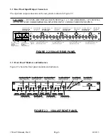
1.) Connect RF cables to the 1584-45 (See Section 2.2).
2.) IF DC VOLTAGE IS REQUIRED ON THE SPLITTER RF INPUT CENTER CONDUCTOR,
install 1/4”, 1 amp fast blo fuses in Fuse 3 and/or Fuse 4 holders.
CAUTION! -- IF FUSES ARE INSTALLED IN THE Fuse 1, 2, 3, or 4 HOLDERS, +22 VDC
WILL APPEAR ON THE CORRESPONDING SPLITTER INPUT CONNECTOR CENTER
PINS.
3.) Connect 100-240 ±10% VAC, 47 - 63 Hz to AC A and AC B on the back panel and observe
A and B LEDs are lit on the front panel.
4.) Monitor RF signals on the front panel monitors and DC voltage to the external amplifiers (Front
panel Green ON LEDs should be lit if LNB fuses are installed in the rear panel fuse holders) to
insure proper signals and voltages.
NOTE: FOR OPTIMUM PERFORMANCE, THE MONITOR PORT AND SPLITTER PORTS
SHOULD BE TERMINATED WITH 75 OHM TYPE F TERMINATIONS WHEN NOT USED.
5.) AC Fuse - The fuse is a 5mm, 2 amp fast blo and is inserted in the far slot in the drawer below
the AC input as shown in Figure 2.6. There is a spare fuse in the near slot. If a fuse continues to
open, the power supply is most likely defective. Note that each power supply module within the
chassis also has a fuse but failure of this fuse indicates the power supply may be defective.
AC Fuse - 2 amp slow blow (Type T),
5 mm X 20 mm
FUSE DRAWER
SPARE FUSE
~
INPUT
100-240± 10%VAC
47-63 Hz
2A MAX
FUSE
TYPE T 2A GDC
250 VOLT
FOR 100 - 240 V~
~
FIGURE 2.4 FUSE LOCATION AND SPARE FUSE
1584-45 Manual, Rev C
Page 7
4/24/13


