


MODEL 1584-45 RF SPLITTER
1.0 General
1.1 Equipment Description
The Model 1584-45 is four, five way, 0.95 - 2.05 GHz, 0 dB gain splitters in a 1 Rack Unit chassis with
redundant 100-240 ±10% VAC power supplies. Each splitter provides fused DC power insertion on the
input connector center pin, surge protection, and excellent RF characteristics. Each splitter has a monitor
connector on the front panel and four outputs on the back panel. Two individual 100-240 ±10% VAC input
power supplies provide a diode OR’d +24 VDC voltage for internal amplifiers and for DC to power
external amplifiers (often Low Noise Block converters or LNBs) through DC power inserters. Each LNB
power line is separately fused. A surge suppressor on each splitter input protects against high voltage
transients. All splitter outputs are AC coupled so no DC appears on their center conductors. On the front
panel, green LEDs indicate presence of +22 VDC at each LNB power supply output and DC voltage test
points allow monitoring this voltage with a voltmeter. Presence of power from the +24 VDC power
supplies is shown by the AC Power A and B green LEDs.
MODEL 1584
1
POWER
SPLITTER
2
ON
LNB VOLTAGE
+DC
GND
RF
MONITOR 1
ON
LNB VOLTAGE
+DC
GND
RF
MONITOR 2
ON
LNB VOLTAGE
+DC
GND
RF
MONITOR 3
ON
LNB VOLTAGE
+DC
GND
RF
MONITOR 4
C
ROSS
T
ECHNOLOGIES INC.
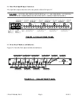
FRONT PANEL
AC A
AC B
GND
JI
J2
J3
J4
J20
J5
J6
J7
J8
J9
J10
J11
J12
J17
J13
J14
J15
J16
OUT
OUT
OUT
OUT
IN
OUT
OUT
OUT
OUT
OUT
OUT
OUT
OUT
IN
OUT
OUT
OUT
OUT
FUSE F4
J18
IN
J19
IN
FUSE F3
FUSE F2
FUSE F1
REAR PANEL
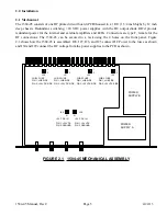
FIGURE 1.1 MODEL 1584-45 FRONT AND REAR PANELS
AMP
DC
INS
SURGE
SUP-
PRESOR
FUSE
LNB PWR LED
1 - 2
GHz
IN
1 - 2 GHz OUT
LNB PWR TP
5 WAY
SPLIT
OUT 1
OUT 2
OUT 3
OUT 4
MON
FIGURE 1.2 MODEL 1584-45 BLOCK DIAGRAM (EACH SPLITTER)
1584-45 Manual, Rev C
Page 3
4/24/13


