


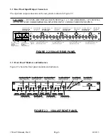


2.2 Rear Panel Input/Output Connectors
The input and output connectors on the rear panel are shown in Figure 2.2.
CAUTION! -- IF FUSES ARE INSTALLED IN THE Fuse 1, 2, 3 OR 4 HOLDERS, +22 VDC WILL
APPEAR ON THE CORRESPONDING SPLITTER INPUT CONNECTOR CENTER PINS.
AC A
AC B
GND
JI
J2
J3
J4
J19
J5
J6
J7
J8
J9
J10
J11
J12
J17
J13
J14
J15
J16
OUT
OUT
OUT
OUT
IN OUT
OUT
OUT
OUT
OUT
OUT
OUT
OUT
IN
OUT
OUT
OUT
OUT
FUSE F4
FUSE F3
SPLITTER 1 OUTPUTS, 75
Ω
Terminate when not used
SPLITTER 1 INPUT, 75
Ω
CAUTION! +22 VDC
ON CENTER PIN
FUSE FOR LNB 3
1 amp Fast Blo,
1/4“ Fuse
AC A INPUT
90 - 260 VAC
47-60 HZ
Uses 2 amp Fast
Blo, 5mm fuse
AC B INPUT
90 - 260 VAC
47-60 HZ
Uses 2 amp Fast
Blo, 5mm fuse
CHASSIS
GROUND
FUSE F2
FUSE F1
J18
IN
J20
IN
FUSE FOR LNB 2
1 amp Fast Blo,
1/4“ Fuse
FUSE FOR LNB 1
1 amp Fast Blo,
1/4“ Fuse
SPLITTER 2 INPUT, 75
Ω
CAUTION! +22 VDC
ON CENTER PIN
SPLITTER 3 INPUT, 75
Ω
CAUTION! +22 VDC
ON CENTER PIN
SPLITTER 4 INPUT, 75
Ω
CAUTION! +22 VDC
ON CENTER PIN
FUSE FOR LNB 4
1 amp Fast Blo,
1/4“ Fuse
SPLITTER 2 OUTPUTS, 75
Ω
Terminate when not used
SPLITTER 3 OUTPUTS, 75
Ω
Terminate when not used
SPLITTER 4 OUTPUTS, 75
Ω
Terminate when not used
AC A INPUT
100-240 ±10% VAC
47-60 HZ
Uses 2 amp
Fast Blo, 5mm fuse
AC B INPUT
100-240 ±10% VAC
47-60 HZ
Uses 2 amp
Fast Blo, 5mm fuse
FIGURE 2.2 1584-45 REAR PANEL
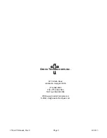
2.3 Front Panel Monitors and Indicators
Figure 2.3 shows the front panel monitors and indicators.
GROUND
TEST POINT
LNB 4 VDC
TEST POINT
DS5 - POWER LED A
Lights green when DC
voltage is present from AC
A power supply.
DS1 - LNB 4 VOLTAGE LED
Lights Green when LNB
voltage is present on the
Splitter input (J17) center pin.
DS6 - POWER LED B
Lights green when DC
voltage is present from
AC B power supply.
MODEL 1584
A
POWER
POWER DIVIDER
B
ON
LNB VOLTAGE
+DC
GND
RF
MONITOR 1
ON
LNB VOLTAGE
+DC
GND
RF
MONITOR 2
ON
LNB VOLTAGE
+DC
GND
RF
MONITOR 3
ON
LNB VOLTAGE
+DC
GND
RF
MONITOR 4
C
ROSS
T
ECHNOLOGIES
INC.
DS2 - LNB3 VOLTAGE LED
Lights Green when LNB
voltage is present on the
Splitter input (J18) center pin.
DS3 - LNB2 VOLTAGE LED
Lights Green when LNB
voltage is present on the
Splitter input (J19) center pin.
GROUND
TEST POINT
LNB 3 VDC
TEST POINT
GROUND
TEST POINT
LNB 2 VDC
TEST POINT
GROUND
TEST POINT
LNB 1 VDC
TEST POINT
DS4 - LNB1 VOLTAGE LED
Lights Green when LNB
voltage is present on the
Splitter input (J20) center pin.
J24 - RF1 MONITOR
Monitors Splitter 1 output.
Type F (female), 75
Ω
.
J23 - RF2 MONITOR
Monitors Splitter 2 output.
Type F (female), 75
Ω
.
J22 - RF3 MONITOR
Monitors Splitter 3 output.
Type F (female), 75
Ω
.
J22 - RF4 MONITOR
Monitors Splitter 4 output.
Type F (female), 75
Ω
.
FIGURE 2.3 1584-45 FRONT PANEL
1584-45 Manual, Rev C
Page 6
4/24/13