Crest Audio FORWARD TECHNOLOGY F-100 Скачать руководство пользователя страница 35

Forward Technology – a Crest Group Company 

Operation and Maintenance Manual for F-100 Cleaning System 


F-100 Manual Rev H 

Non-Flammable 

34 

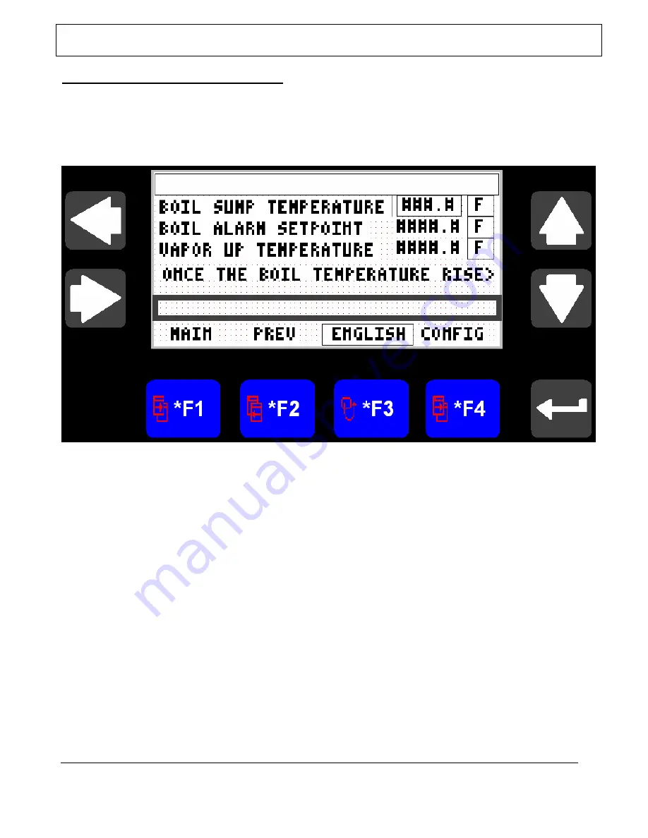
PROCESS PARAMETERS: OEM (Continued) 


WARNING: All of these settings are Factory set and should not be changed unless 

authorized by Forward Technology Inc. 


OEM: FTI 


Figure 27: FTI 

 
Right Arrow = Not Used 
Left Arrow = Not Used 
Up Arrow = Select Numeric Entry 
Down Arrow = Select Numeric Entry 
F1 = Go To Main Menu 
F2 = Go To Previous Screen (Alarm History) 
F3 = Change Display Temperature English/Metric 
F4 = Go To Configuration Screen, Not Used, FTI Service ONLY 


WARNING: All of these settings are Factory set and should not be changed unless authorized by Forward 

Technology Inc. 

Содержание FORWARD TECHNOLOGY F-100

Страница 1: ...TION AND MAINTENANCE MANUAL FOR SOLVENT CLEANING MACHINES FOR USE WITH NON FLAMMABLE PERFORMANCE SOLVENTS FORWARD TECHNOLOGY a Crest Group Company 1886 Berkshire Lane North MINNEAPOLIS MN 55441 www crest ultrasonics com TEL 763 559 1785 FAX 763 559 3929 ...

Страница 2: ...NUAL MODE ____________________________________________________20 PROCESS PARAMETERS ____________________________________________23 PROCESS PARAMETERS Continued __________________________________24 SETUP_1__________________________________________________________24 SETUP_2 Oscillation ________________________________________________25 DATE____________________________________________________________...

Страница 3: ...ravity drains into the wash sump which cascades into the boil sump As parts are lowered into the cleaner solvent condenses onto the parts rinsing them Sonication of the parts once immersed in the tank removes particulate A final rinse takes place in solvent vapor as the parts are removed from the process tank Solvent remaining on the parts volatizes and drops back into the tank when moved into the...

Страница 4: ... COOLING Cooling coils reduce solvent emissions by condensing solvent vapors in the upper tank INSTRUMENTATION AND CONTROL The system is controlled through an Allen Bradley Programmable Logic Controller PLC The PLC controls process parameters System software is developed by Forward Technology The PLC and all electrical components are contained in an on board electrical enclosure The operator contr...

Страница 5: ...haust in the tank for 24 hours Maintenance personnel entering an evacuated degreaser must be provided with safety equipment such as gas tight goggles and airline mask with proper regulators and filters or self sustained breathing equipment All solvent containers should be properly identified with appropriate warning labels Store all containers of solvent in proper storage cabinets Avoid inhalation...

Страница 6: ...er Solvent STARTUP PROCEDURE 1 Place the main power disconnect in the ON position The main power disconnect is located on the main enclosure The compressor system and display should come on Figure 1 Main Disconnect 2 Clear all alarms possible some alarms will not allow the system to power up they will always be triggered after the MAIN DISCONNECT switch is cycled NOTE some alarms will still exist ...

Страница 7: ...Machine Ready will be displayed 9 To load parts into the machine all alarms recorded to the alarm log are required to be cleared Clear any alarms currently active 10 Open the cover and place the parts to be cleaned in the machine by touching the COVER OPEN button located on the display panel 11 Press the CYCLE START button located on the main enclosure the cleaning cycle will begin and the timers ...

Страница 8: ...HUTDOWN Solvent Is To Be Removed From Machine When the cleaning cycle is complete and All baskets have been removed from the machine then Press the MAIN SCREEN button in the upper right corner of the screen to return to the Main Menu Press the COOLDOWN button to remove the machine from automatic and start the cool down of the solvent 1 It is recommended that the solvent be allowed to cool to room ...

Страница 9: ...n the main enclosure Figure 6 Control Power Off E Stop Buttons 2 The cleaning system will automatically shut off the heating system and allow the sump to cool NOTE This will not kill the power to the cooling system as it is a greater safety risk to not provide vapor containment DO NOT shut off the main power until the solvent is at room temperature Turning off the main power before the solvent is ...

Страница 10: ... above the float switch minimum 2 The second is outlined below using the bulkhead connections a transfer pump not included Filling the F 100 using bulkhead connections 1 Hook a fill hose pump not included to the wash sump bulkhead connection Figure 7 Outside Bulkhead Figure 8 Inside Bulkhead 2 Open the wash sump ball valve connected to the wash sump Figure 9 Tank Ball Valves 3 Start the pump this ...

Страница 11: ...er housings and recirculation lines Add solvent as required 5 When system is full disconnect the solvent supply DRAINING 1 Select the sump you want to drain Connect the drain hose to the Selected sump bulkhead connection Figure 10 Bulkhead 2 Open the ball valve to the tank Figure 11 Tank Ball Valves 3 Drain the selected sump Use care not to overflow the container Open to drain WASH SUMP Open to dr...

Страница 12: ...NING PARTS LOADING BASKET Parts to be cleaned in the system should be arranged to allow proper drainage Retention of solvent in holes cavities etc will result in excessive solvent drag out which will increase emissions WASH RINSE TIME Most cleaning cycle times are usually 1 5 minutes Testing will determine the proper dwell times for each part or basket ...

Страница 13: ... available to the operator using the interface control panel screens Upon powering up the machine or after exiting one of the operating modes the operator interface control panel will display the Main Menu screen shown below From this menu all machine operations are selected Figure 12 Main Screen Right Arrow When Control Power Is On Close Tank Cover Left Arrow When Control Power Is On Open Tank Co...

Страница 14: ...parts processing COOLDOWN Figure 15 Select this mode to cool down the system and when the system will not be use for part processing MENU Figure 17 These screens are used to enter fixed machine parameters manually toggle I O points PASSWORD Figure 16 MANUAL Figure 18 19 SETUP_1 Figure 20 SETUP_2 Figure 21 DATE Figure 22 OEM Figure 23 CONFIG Figure 24 AVERAGE Figure 25 LIFT Figure 26 FTI Figure 27 ...

Страница 15: ... parameters while running process Current recipe times and time remaining seconds is displayed on this screen Figure 13 Auto 1 Screen Right Arrow When Control Power Is On Close Tank Cover Left Arrow When Control Power Is On Open Tank Cover Up Arrow Not Used Down Arrow Not Used F1 Go To Main Menu F2 Go To Next Screen Auto Mode Two F3 Cover Man Cover Always Open Auto Cover will close during cycle F4...

Страница 16: ...layed on this screen sump temperatures superheated vapor temperatures and refrigeration temperatures F or C Figure 14 Auto 2 Screen Right Arrow When Control Power Is On Close Tank Cover Left Arrow When Control Power Is On Open Tank Cover Up Arrow Not Used Down Arrow Not Used F1 Go To Main Menu Screen F2 Go To Previous Screen Auto Mode One F3 Change Display Temperature English Metric F4 Reset Alarm...

Страница 17: ...ate preventing solvent vapors from exiting the system through the cover access This screen allows the operator to view the current condition of the machine without generating heat or vapor Figure 15 Cool down Right Arrow When Control Power Is On Close Tank Cover Left Arrow When Control Power Is On Open Tank Cover Up Arrow Not Used Down Arrow Not Used F1 To Go Main Menu F2 To Auto Mode Screen One S...

Страница 18: ...GE FTI factory settings LIFT FTI factory settings FTI_INFO FTI Machine Info PV_CONFG Panel View factory settings All of these screens can be accessed through the MENU screen SETUP_1 SETUP_2 TIME DATE OEM screens are authorized to be modified in the field to meet customer requirements WARNING All other screens are set at the factory and should not be changed without authorization All of these scree...

Страница 19: ... two functions 1 Shows a history of the alarm log since the last power up 2 Allows access to parameter setup screens Figure 17 MENU Right Arrow Reset Alarms Left Arrow Alarm List Up Arrow Scroll Up Alarm Active List Down Arrow Scroll Down Alarm Active List F1 Go To Main Menu Screen F2 Go To Manual Mode Screen One F3 Go To Setup Screen F4 Go To Alarm History Screen ...

Страница 20: ... Cleaning System F 100 Manual Rev H Non Flammable 19 Right Arrow Reset Alarms Left Arrow Alarm List Up Arrow Scroll Up Alarm History List Down Arrow Scroll Down Alarm History List F1 Go To Main Menu Screen F2 Go To Manual Mode Screen One F3 Go To Setup Screen F4 Go To OEM Setup Screen ...

Страница 21: ... override pressing it again will cancel the override In addition pressing the opposite manual button will cancel the existing override and enable the selected override When activated the state of the output will flash as an indicator to reflect the state or position of the mechanism To test the output from the manual screens you need to do the following 1 Select the desired output to function 2 Se...

Страница 22: ...mable 21 MANUAL MODE continued Figure18 Manual 1 Screen Right Arrow Not Used Left Arrow Not Used Up Arrow Select Numeric Entry Down Arrow Select Numeric Entry F1 Go To Main Menu F2 Go To Next Screen Manual Two F3 Enable Manual Force On F4 Enable Manual Force Off WARNING Before exiting the manual screen remove all forced states ...

Страница 23: ...ble 22 MANUAL MODE continued Figure19 Manual 2 Screen Right Arrow Not Used Left Arrow Not Used Up Arrow Select Numeric Entry Down Arrow Select Numeric Entry F1 Go To Main Menu F2 Go To Previous Screen Manual One F3 Enable Manual Force On F4 Enable Manual Force Off WARNING Before exiting the manual screen remove all forced states ...

Страница 24: ...ure in this region excessive cooling time could result in condensation on the parts after removal from the machine A time of zero will result in the basket passing directly through the freeboard region NOTE The combined time for Wash Soak Wash Ultrasonic must be a minimum of 20 seconds NOTE The Vapor Soak and Dry Times also have an individual minimum of 20 seconds each OPTIONAL FEATURE OSCILLATION...

Страница 25: ...ess step all machines have this as a minimum Figure 20 SETUP_1 Screen Right Arrow Scroll Forward Numeric Entry Left Arrow Scroll Backward Numeric Entry Up Arrow Select Numeric Entry Down Arrow Select Numeric Entry F1 Go To Main Screen F2 Go To Oscillation Screen F3 Run Auto Cycle With Ultrasonic Time 1 st 2 nd F4 Reset Alarms WARNING If the value does not change the minimum or maximum value may ha...

Страница 26: ... is not installed on all machines If it is not installed the screen will either not be available or the fields will not be accessible Figure 21 SETUP_2 Screen Right Arrow Not Used Left Arrow Not Used Up Arrow Select Numeric Entry Down Arrow Select Numeric Entry F1 Go To Previous Screen Setup Menu One F2 Go To Time Date Screen F3 Run Auto Cycle With Oscillation 1 st 2 nd During Immersion Time F4 Re...

Страница 27: ...screen shows the total cycle counts for the machine and allows for the time date to be modified Figure 22 Date Screen Right Arrow Scroll Forward Numeric Entry Left Arrow Scroll Backward Numeric Entry Up Arrow Select Numeric Entry Down Arrow Select Numeric Entry F1 Go To Main Menu Screen F2 Go To Previous Screen Setup Two F3 Go To Option Menu Screen Active Alarms F4 Reset Alarms ...

Страница 28: ...larm Set Point This value is the value used for alarm set point it is set at 10 degree s F above the boil set point This alarm indicates that the solvent in the boil is over contaminated and needs to be replaced Vapor Up Temperature This value is the temperature at which the vapor blanket has been achieved NOTE Changing solvent type will likely require the OEM Settings be adjusted OEM CONFIG SCREE...

Страница 29: ...O The Average displays timer representing when the sample X above being displayed was taken CYCLE COUNTER Total machine cycles OEM LIFT SCREEN CYCLER The counter for the 1000 cycle repeat option BRAKE The delay timer for the lift motor raise to allow the brake to function BRAKE The preset timer for resetting the TC CARD ERROR alarm trigger LIFT E The timer for triggering LIFT POSITION ERROR alarm ...

Страница 30: ...less authorized by Forward Technology Inc OEM Figure 23 OEM Screen Right Arrow Not Used Left Arrow Not Used Up Arrow Select Numeric Entry Down Arrow Select Numeric Entry F1 Go To Main Menu F2 Go To Previous Screen Alarm History F3 Change Display Temperature English Metric F4 Go To Configuration Screen Not Used FTI Service ONLY WARNING All of these settings are Factory set and should not be changed...

Страница 31: ...thorized by Forward Technology Inc OEM CONFIG Figure 24 Config Screen Right Arrow Scroll Forward Numeric Entry Left Arrow Scroll Backward Numeric Entry Up Arrow Select Numeric Entry Down Arrow Select Numeric Entry F1 Go To Main Menu Screen F2 Go To Previous Screen Average F3 Go To Lift Parameters Screen F4 Go To Configuration 2 Screen WARNING All of these settings are Factory set and should not be...

Страница 32: ...al Rev H Non Flammable 31 Configuration 2 FTI ONLY Right Arrow Scroll Forward Numeric Entry Left Arrow Scroll Backward Numeric Entry Up Arrow Select Numeric Entry Down Arrow Select Numeric Entry F1 Go To Main Menu Screen F2 Go To Previous Screen Configuration One F3 Go To Lift Parameters Screen F4 Reset Alarms ...

Страница 33: ...less authorized by Forward Technology Inc OEM AVERAGE Figure 25 AVERAGE Right Arrow Scroll Forward Numeric Entry Left Arrow Scroll Backward Numeric Entry Up Arrow Select Numeric Entry Down Arrow Select Numeric Entry F1 Go To Main Menu Screen F2 Go To Next Screen Configuration One F3 Cycle Repeat Enabled Disabled F4 Reset Alarms WARNING All of these settings are Factory set and should not be change...

Страница 34: ...horized by Forward Technology Inc OEM LIFT Figure 26 LIFT Right Arrow Scroll Forward Numeric Entry Left Arrow Scroll Backward Numeric Entry Up Arrow Select Numeric Entry Down Arrow Select Numeric Entry F1 Go To Main Menu Screen F2 Go To Previous Screen Configuration Two F3 Go To FTI Info Screen F4 Go To AB Panelview Configuration Menu WARNING All of these settings are Factory set and should not be...

Страница 35: ...unless authorized by Forward Technology Inc OEM FTI Figure 27 FTI Right Arrow Not Used Left Arrow Not Used Up Arrow Select Numeric Entry Down Arrow Select Numeric Entry F1 Go To Main Menu F2 Go To Previous Screen Alarm History F3 Change Display Temperature English Metric F4 Go To Configuration Screen Not Used FTI Service ONLY WARNING All of these settings are Factory set and should not be changed ...

Страница 36: ... more detail in the following pages The ALARM button can be selected from any of the system s operator interface screens When an alarm is active and requires intervention the alarm message will be displayed on the main screen In addition to this an audible buzzer will sound alerting the operator to the presence of the alarm To reset an alarm and to silence the buzzer press the ALARM button This wi...

Страница 37: ... Cleaning System F 100 Manual Rev H Non Flammable 36 Right Arrow Reset Alarms Left Arrow Alarm List Up Arrow Scroll Up Alarm History List Down Arrow Scroll Down Alarm History List F1 Go To Main Menu Screen F2 Go To Manual Mode Screen One F3 Go To Setup Screen F4 Go To OEM Setup Screen ...

Страница 38: ...of each Suggested methods for troubleshooting many of the alarms are also included CONDENSING COIL TC BROKEN VAPOR TC BROKEN BOIL SUMP TC BROKEN HIGH VAPOR TC BROKEN These alarms state that one or more of the F 100 Series thermocouples has broken or is reading outside of a specified range Some possible causes for this alarm are listed below Check to see that the appropriate thermocouple has not be...

Страница 39: ...ailed Figure 30 Float Switch Check the level of the solvent to ensure it is higher than the float switch If it is low fill the machine with solvent using the procedure listed under Filling and Draining Solvent in this manual try to clear the alarm If the alarm continues check the float switch for proper operation BOIL CONTAIMINED The solvent temperature has risen 10 degree s above boiling point re...

Страница 40: ...ce Dirty evaporator coils need to be cleaned inside rear panel of machine Airflow to the evaporator coils is restricted Unit tripped by high head pressure reset Figure 31 Thermal Overload Reset SAFETY CIRCUIT INTERRUPTED The Heater Over Temp relay or Vapor Over Temp relay alarms are active To confirm which one is tripped you can check the low voltage signal on the over temp relays The relay showin...

Страница 41: ...when control power is on Figure 33 Control Panel Press the CONTROL POWER ON button try to clear the alarm If the alarm does not clear troubleshoot the control power circuit SAFETY CIRCUIT ERROR The safety circuit has failed allowing control power to be on The system recognizes this failure and has alarmed as such This can be caused by a misplaced jumper or other rewiring issue Check the electrical...

Страница 42: ...ued TC CARD ERROR The PLC has detected an issue with the thermocouple card Figure 35 TC Card COVER SWTICH ERROR No tank cover sensors are active COVER FAILED TO OPEN The tank cover door did not open Figure 36 Cover Access 1 Figure 37 Cover Access 2 WARNING Be cautious regarding the wires hanging from the upper enclosure to the lower enclosure when moving the upper cover ...

Страница 43: ...SAGES EXPLANATIONS Continued COVER FAILED TO CLOSE The tank cover door did not close COVER ERROR DURING PROCESS Cover door not open closed while processing COVER NOT ATTACHED TO DRIVE Cover door not moving when drive is running Figure 38 Cover Magnet COVER MOTOR ERROR Cover failed to open close within the time limit Figure 39 Cover Motor Sensors ...

Страница 44: ...Flammable 43 ALARM MESSAGES EXPLANATIONS Continued LIFT POSITION ERROR No Lift Position Sensors Active LIFT NOT AT HOME Lift Not To Home Position Sensor LIFT NOT AT IMMERSION Lift Not To Immersion Position Figure 40 Lift Assy LIFT NOT AT VAPOR Lift Not To Vapor Position Sensor LIFT NOT AT DRY Lift Not To Dry Position Sensor ...

Страница 45: ...rest Group Company Operation and Maintenance Manual for F 100 Cleaning System F 100 Manual Rev H Non Flammable 44 ALARM MESSAGES EXPLANATIONS Continued LIFT MOTOR ERROR Lift Failed To Reach Next Position Figure 41 Lift Motor ...

Страница 46: ...oblem Reset Alarms CONTROL POWER IS OFF Control Power Is Off SYSTEM IS AT TEMPERATURE F 100 Is Up To Temperature PRESS CYCLE START TO BEGIN PROCESSING BASKET Press Cycle Start BASKET PROCESSING Machine Is Processing A Basket SYSTEM IS WARMING UP Machine Is Warming Up TANK COVER IS OPENNING Tank Cover Is Opening TANK COVER IS CLOSING Tank Cover Is Closing LIFT IS RAISING Lift Is Raising To Next Pos...

Страница 47: ...hey are all filled to the proper operating levels Check operation of the refrigeration equipment check sight glasses should be clear and dry Upon starting the system each day observe the time required for vapors to rise and stabilize at the proper level Also observe the vapor level when parts are put into the vapor zone If there is a notable change in either the system may require cleaning Check t...

Страница 48: ...Perform a complete safety check See the last page of this manual 1 Remove the cover panels and check for leaks in the plumbing lines pump housings and other wet process components 2 Check refrigeration condensers for damaged fins dirt and excessive noise If any problems occur repairs should be performed by a Licensed Refrigeration Technician 3 Check all pumps for excessive noise 4 TURN OFF THE ELE...

Страница 49: ...nsed Refrigeration Technician If the unit is in a location where the condenser is exposed to dust and dirt more frequent inspections may be necessary Below are the items the Licensed Refrigeration Technician must inspect 1 Operating pressures and temperatures 2 Clean Condenser 3 Inspect Condenser fan bearings and oil if req d 4 Inspect each refrigerant sight glass for moisture and bubbles 5 Check ...

Страница 50: ...ve the clean out door from the boil sump Remove the heating rods from the boil sumps clean the exterior surface inspect for any hot spots or signs of damage Evacuate the system before entering for clean up or maintenance This is achieved by removing the clean out door on the boil sump and blowing fresh air into the system for 3 4 hours Or pull an exhaust in the tank for 24 hours Maintenance person...

Страница 51: ..._____ 1 Check each input signal on the PLC _____ 2 Check each control valve _____ 3 Disconnect each thermocouple and ensure the correct alarm is displayed _____ 4 Fill tanks with solvent and check for leaks _____ 5 Set operating parameters for the solvent being used _____ 6 Select the Auto Mode and allow the system to reach operating temperature Checked by ____________________________________ ...

Страница 52: ...__ Options Oscillation Spare Parts Kit Number ___________________________ Std Double Open End Filter housing 222 Style Filter housing Other ___________________________________________ S W PLC ____________________________________________________ S W HMI _____________________________________________________ Chemical Selected _____________________________________________ Filter Selected _____________...

Страница 53: ... 1 1 System Password NOTE System passwords are hard coded and not changeable via the user Setup Screen Password Manual 1785 OEM 13500 Setup Change Recipe 1 1 2 Correction for page 9 10 Figure 7 Outside Bulkhead 1 1 ...

Страница 54: ...Figure 8 Inside Bulkhead Figure 10 Bulkhead 1 2 ...

Страница 55: ...ollect in the immersion sump and none will flow back over into the boil sump 6 At some point the machine will alarm for low solvent level in the boil sump This will automatically shut off the heaters and turn the control power off to the machine the refrigeration will remain on 7 Drain the now minimized contents of the boil sump into and a waste container appropriate for the solvent being used 8 M...

Страница 56: ...1Ø refer to electrical drawing for more detail Turn Red Knob 90 Clockwise to ON position 2 Make Certain both drain valve handles are closed Valve handle is horizontal as shown below Check water separator condensate reservoir drain valves Handles need to perpendicular to the valve body to be closed 3 4 ...

Страница 57: ...101012 take 9 0 gallons x Pour some fluid into condensate trough as pointed with blue arrow on picture above to fill condensate water separator reservoir x Immersion sump overflows to fill boil sump x Check sight tube on the lower left front of the system Boil sump is full when solvent is above the top of sight tube 4 This step 3 will allow Boil Sump Low Level alarm to be cleared 3 5 ...

Страница 58: ...button on picture below x When the button s indicator green light is ON normal operation is now possible 7 x Press F1 twice to change the status from Cool Down mode to Automatic mode x Heater and recirculation pump will turn ON x The system will take about 20 min to heat up the solvent The heat up time is depended on the solvent used 3 6 ...

Страница 59: ...o move to next digit o press down key to set second digit to 7 o repeat step above until the password is displayed o press on Enter key 10 x Process Recipe Page as shown will prompt x Move the cursor to the process Recipe Number box and set the process time using the Right and Left key x Press on Enter key to enter the recipe number x Repeat step above to set up process time for the other 4 proces...

Страница 60: ... Right key to change the recipe x Press F1 Auto to return to Main Screen x Press F1 Auto again to go to Process Recipe screen The new process recipe will be displayed x Press Cycle Start button the appropriate process parameters for the new process shall be displayed on the process screen 12 System is now ready for Auto Cycle Load basket and press on Cycle Start Button Solid Green button 3 8 ...

Страница 61: ...se and Left key open at least once to engage automatic operation 14 Cool down x When machine is not going to be used for several hours press F2 to place the system to Cool Down mode x In Cool Down mode system will turn OFF the boil sump heater and recirculation pump x Note the main power must remain ON when ever solvent is in the machine 3 9 ...

Страница 62: ...mmediately Refer to plumbing drawing for valve number 5 Open the drain valve to drain solvent from filter to a safe container Dispose solvent according to your local regulations 6 Unscrew the cover nut being certain to support shell with hand 7 Remove the cartridge from shell by pulling up through the open top of the shell Dispose of cartridge properly according to your local trash regulations 8 C...

Страница 63: ...ver the center rod and through the open top of the clean shell 11 Re install shell on filter head by tightening the cover nut Avoid over tightening not exceed 10 foot pounds of torque or you will damage the head and shell 12 Close drain valve at bottom part of filter housing and open isolated valves 4 11 ...

Отзывы: