background image

C-2 Troubleshooting

5. In the Properties dialog box, click the Settings 

tab and ensure that the Auto Insert Notification 
check box is selected.

6. Click the OK button to you exit from the

 dialog box.

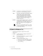
Problems with Sound

Problem

No output from both the 8-bit and 16-bit digitized 
sounds when running the test program.

Causes

The volume knob on the speakers is not set properly.

The external amplifier or speakers are connected to 
the wrong jack.

The speaker amplifiers are in the On position.
If you are using powered speakers in a non-powered 
state, turn off their amplifiers.

There is hardware conflict.

Solution

Verify the following:

Volume control knob of the speakers, if any, is set at 
mid-range.

Speakers are connected to the Speaker Out jack.

External amplifier or powered speakers are 
connected to the card’s Line Out jack(s) if you do 
not have or decide not to use the card’s internal 
power amplifier.

The speaker amplifiers are in the Off position.

No hardware conflict between the card and a 
peripheral device.  For details, see “Resolving 
Hardware Conflicts” on page C-5.

This manual downloaded from http://www.manualowl.com

Содержание Sound Blaster 16

Страница 1: ...Sound Gen plug play Cdr GS ENGLISH TM Getting Started Plug and Play This manual downloaded from http www manualowl com ...

Страница 2: ...he terms of the license agreement It is against the law to copy the software on any other medium except as specifically allowed in the license agreement The licensee may make one copy of the software for backup purposes Copyright 1997 by Creative Technology Ltd All rights reserved Version 2 0 October 1997 Sound Blaster is a registered trademark of Creative Technology Ltd Sound Blaster 16 and Wave ...

Страница 3: ...ferent from that to which the receiver is connected Consult the dealer or an experienced radio TV technician Caution To comply with the limits for the Class B digital device pursuant to Part 15 of the FCC Rules this device must be installed in computer equipment certified to comply with the Class B limits All cables used to connect the computer and peripherals must be shielded and grounded Operati...

Страница 4: ...ows 3 1x Installing the Software 3 1 Testing the Installation 3 2 Optimizing Memory Usage 3 2 Using Memory Managers 3 3 A Understanding the Installation Understanding the Software Configurable Settings A 1 Input Output I O Addresses A 2 Interrupt Request IRQ Lines A 3 Direct Memory Access DMA Channels A 3 Understanding the Environment Variables A 3 SOUND Environment Variable A 4 BLASTER Environmen...

Страница 5: ...rnal Speakers D 2 AUX1 Connector Pin Assignments D 3 AUX2 Connector Pin Assignments D 3 CD Audio Connector Pin Assignments D 4 DRAM Upgrade Connector Pin Assignments D 5 Gold Finch Connector Pin Assignments D 7 IDE Connector Pin Assignments D 7 Microphone Connector Pin Assignments D 8 Modem Connector Pin Assignments D 9 PC Speaker Connector Pin Assignments D 9 SPDIF Connector Pin Assignments D 10 ...

Страница 6: ...audio software in Windows 95 and Windows 3 1x respectively For information on installation changing settings and troubleshooting see the appendices Getting More Information Refer to the Knowing Your Audio Card leaflet to familiarize yourself with the key features of your audio card Refer to the online User s Guide for MIDI specifications and connector pin assignments as well as instructions on how...

Страница 7: ... DOS command line it is a placeholder that represents information you must provide This information usually appears in the parameter listing after the command is presented UPPERCASE Directory name file name or acronym Symbols letters and key names on the keyboard Figure i Elements of a dialog box Tabs Check box selected Option buttons Up Down buttons Drop down list box Text box List box Check box ...

Страница 8: ...nstall a PnP configuration manager For details refer to the documentation that comes with your PnP configuration manager To install the card and related peripherals 1 Switch off your system and all peripheral devices and unplug the power cord from the wall outlet 2 Touch a metal plate on your system to ground yourself and discharge any static electricity 3 Remove the cover from your system This ma...

Страница 9: ... card into the freeslot as shown 7 Secure the card to the expansion slot with the screw that you removed from the metal plate 8 Connect powered speakers or an external amplifier to the Line Out jack s if your audio card does not have an internal amplifier or if you do not want to use the amplifier You can also connect non powered speakers to your audio card s Speaker Out jack Refer to the Knowing ...

Страница 10: ...ep 4 you can test it as follows 1 Make sure that you have installed the audio software The installation of the software is covered in the next two chapters 2 Start the AWE Control Panel That is click the Start button point to Programs point to the menu of your Sound Blaster card and then click AWE Control Panel 3 Load SoundFont banks That is click the User tab click the Browse button to browse for...

Страница 11: ...Drivers You need device drivers to control the components on your audio card After you have installed the card and switched on your system Windows 95 automatically detects the components and either installs the drivers or prompts you for the drivers You may encounter the following messages which may not be in the sequence shown If a message similar to Figure 2 1 appears just take note of it and wa...

Страница 12: ...f you are prompted for the Windows 95 installation diskette or CD ROM insert it into a drive and click the OK button If a dialog box similar to Figure 2 3 appears click the second option and then click the OK button Figure 2 2 Driver installation dialog box in which the Windows default driver option is available Figure 2 3 Driver installation dialog box in which the Windows default driver option i...

Страница 13: ...appropriate drive and click the OK button Otherwise 1 Insert the installation CD ROM into your CD ROM drive and select the drive 2 Click the Browse button and look for a INF file in the root directory If you cannot find it select the folder WIN95 Language DRIVERS where Language is the language of the software that you want to install 3 Click the OK button The required files are copied to your hard...

Страница 14: ... the screen to complete the installation To install from diskettes 1 Insert the first installation diskette into your floppy disk drive 2 Click the Start button and then click Run 3 In the Run dialog box type A SETUP or B SETUP 4 Click the OK button and follow the instructions on the screen to complete the installation Testing the Installation After the applications are installed you can use Windo...

Страница 15: ...the Details button 5 In the Multimedia dialog box make sure that the Media Player check box is selected If you do not have Volume Control Sound Recorder or Audio Compression installed make sure that the relevant check boxes are also selected 6 Follow the instructions on the screen to complete the installation Figure 2 5 Windows Setup tabbed page This manual downloaded from http www manualowl com ...

Страница 16: ...bleshooting Uninstalling the Applications The Windows 95 Uninstall feature allows you to remove applications cleanly and then reinstall them to correct problems change configurations or make version upgrades Quit the audio card s applications before uninstalling Applications that are still running during uninstallation will not be uninstalled Some applications may share files with other Windows ap...

Страница 17: ...2 Double click the Add Remove Programs icon 3 In the Add Remove Programs Properties dialog box select the Sound Blaster entry for your card see the Knowing Your Audio Card leaflet for your exact card model and click the Add Remove button 4 Follow the instructions on the screen to uninstall This manual downloaded from http www manualowl com ...

Страница 18: ...install the software 1 If your package comes with installation diskettes insert the first installation diskette into a floppy disk drive Otherwise insert the installation CD ROM into your CD ROM drive 2 Select Run from the File menu 3 Type D WIN31 DISK1 SETUP and press Enter 4 Follow the instructions on the screen to complete the installation After you have completed the installation and rebooted ...

Страница 19: ... it may be due to a conflict between the audio card and another peripheral device To resolve the conflict you have to change the settings of your audio card For more information see Appendix A Understanding the Installation or Appendix C Troubleshooting Optimizing Memory Usage If you choose to install the low level DOS device drivers under custom installation see The CONFIG SYS File Settings on pa...

Страница 20: ... Create a session with settings that load the drivers into memory If you do not want to load these drivers select another session without them at system bootup Refer to your MS DOS 6 x documentation for instructions on how to create multiple boot sessions To use a memory manager If you are using MS DOS 6 x run MEMMAKER For details refer to your MS DOS 6 x documentation If you have a memory manager...

Страница 21: ...rces such as I O addresses interrupt lines and DMA channels to your card when you install it If you are using Windows 95 this PnP operating system will automatically set up your card s resources If you are using a non PnP system such as Windows 3 1x you must run a PnP configuration manager to configure the card For details refer to the documentation on your PnP configuration manager This section e...

Страница 22: ...es are communication areas used by your computer s central processor to distinguish among various peripheral devices connected to your system when sending or receiving data Refer to General Specifications of the Knowing Your Audio Card leaflet to find out which devices marked are available on your card Table A 1 Possible default I O addresses used by the various devices on the audio card I O Addre...

Страница 23: ...onment Variables Environment variables are used to pass hardware configuration information to software in your system This section explains the environment variables of your audio card SOUND Environment Variable BLASTER Environment Variable only DOS applications use this MIDI Environment Variable applicable only in DOS for the PLAY utility Table A 2 Possible default IRQ line assignments for audio ...

Страница 24: ...ystem No space is allowed before and after the equal sign However there must be at least a space between parameters The parameters in the command and their possible default values are as follows This Parameter Specifies Axxx Audio interface s base I O address xxx defaults to 220 Ix IRQ line used by the audio interface x defaults to 5 Dx Low DMA channel used by the audio interface x defaults to 1 H...

Страница 25: ... described below This Parameter Specifies SYNTH x Synthesizer type x can be 1 or 2 1 default setting specifies the stereo music synthesizer 2 specifies the MIDI port MAP x File format x can be G E or B G specifies the General MIDI file format E default setting specifies the Extended MIDI file format B specifies the Basic MIDI file format MODE x Synthesizer mode x can be 0 1 or 2 0 default setting ...

Страница 26: ...were not installed previously The installation program also modifies your AUTOEXEC BAT and CONFIG SYS files The AUTOEXEC BAT File Settings The installation program adds the following statements to the AUTOEXEC BAT file SET BLASTER A220 I5 D1 H5 P330 E620 T6 SET SOUND C SB16 SET MIDI SYNTH 1 MAP E MODE 0 C SB16 DIAGNOSE S W C WINDOWS C SB16 MIXERSET P Q C SB16 AWEUTIL S The directory name SB16 may ...

Страница 27: ...river name CTSB16 SYS may be VIBRA16 SYS in your installation CTSB16 SYS or VIBRA16 SYS and CTMMSYS SYS are low level device drivers that provide wave playback and recording for DOS applications including third party DOS applications developed using drivers such as CTWDSK DRV CTWMEM DRV CTVDSK DRV and CT VOICE DRV that require these low level drivers The drivers are found in the DRV subdirectory o...

Страница 28: ...es Enabling Disabling Creative 3D Stereo Enhancement Effect The Creative 3D Stereo Enhancement 3DSE effect allows you to eliminate speaker crosstalk which occurs when two speakers are placed close together With this effect enabled mono and stereo sounds produced by your speakers will have increased depth and breadth If your pair of speakers or another device already has a built in 3D sound technol...

Страница 29: ...lers 5 Select the Creative Sound Blaster entry for your audio card and click the Properties button 6 In the Properties dialog box click the Settings tab 7 To enable the Creative 3D Stereo Enhancement effect make sure that the Enable Creative 3D Stereo Enhancement check box is selected To disable the effect clear the check box 8 Click the OK button Enabling Disabling Full Duplex Operation The full ...

Страница 30: ...heck box is selected To disable the operation clear the check box 3 Click the OK button Enabling Disabling MPU 401 MIDI Emulation The MPU 401 MIDI Emulation feature allows most real mode games which do not support wavetable synthesis to play wavetable music from the audio card The MIDI output from the games is directed to the wavetable synthesizer rather than the MPU 401 interface Games that have ...

Страница 31: ... the settings shown in Figure B 1 To enable or disable MPU401 emulation in Windows 95 1 Start AWE Control Panel 2 In AWE Control Panel click the Device button 3 In the Device Selection dialog box make sure that the Allow MPU401 Emulation On This Device check box is selected and then click the Select button 4 In AWE Control Panel click the Quit button Figure B 1 Available MPU 401 MIDI Emulation set...

Страница 32: ...ources window displays the current resources assigned to the interface 6 To enable the interface clear the check box To disable it make sure the Disable check box is selected 7 Click the OK button twice 8 On the Menu click Exit Type the path of your Windows 3 1x directory for example C Windows and press Enter 9 Restart your system for the change to take effect To enable or disable the interface in...

Страница 33: ...e effect After restarting Windows 95 ignore the information displayed in the Resource Settings box on the Resources tabbed page of the dialog box The only indicator that your interface has been disabled is the cleared Original Configuration Current check box or the selected Disable In This Hardware Profile check box When you re enable the interface for use by another device Windows 95 might warn y...

Страница 34: ... Solution To enable AutoPlay Through the My Computer shortcut menu 1 Double click the My Computer icon on your Windows 95 desktop 2 In the My Computer window right click the CD ROM drive icon 3 On the shortcut menu click AutoPlay and follow the instructions on the screen Through Auto Insert Notification 1 Click the Start button point to Settings and then click Control Panel 2 In the Control Panel ...

Страница 35: ...ifiers are in the On position If you are using powered speakers in a non powered state turn off their amplifiers There is hardware conflict Solution Verify the following Volume control knob of the speakers if any is set at mid range Speakers are connected to the Speaker Out jack External amplifier or powered speakers are connected to the card s Line Out jack s if you do not have or decide not to u...

Страница 36: ...environment in the respective system files run DIAGNOSE see Understanding the Installation on page A 1 To set up the SOUND environment insert the statement SET SOUND C SB16 into the AUTOEXEC BAT file using a text editor Reboot your system for the changes to take effect The directory name SB16 may be VIBRA16 in your installation Problem Error message Out of environment space Cause The system enviro...

Страница 37: ...guration utility and select a configuration that uses Low DMA channel only 16 bit audio data will then be transferred through the Low DMA channel When you set your High DMA channel to Low DMA you will lose the full duplex operation which requires two separate DMA channels Problems in Windows 3 1x The following are problems you might encounter when in Windows 3 1x Problem No sound is heard when run...

Страница 38: ... be different in your system The parameters in bold apply only to Sound Blaster SB32 and the AWE line of audio cards If one or more of the statements are missing run SETUP in the audio software directory SETUP rewrites SYSTEM INI to set up the drivers and the Windows applications Resolving Hardware Conflicts Hardware conflicts occur when two or more peripheral devices contend for the same resource...

Страница 39: ...Video And Game Controllers 5 Select your audio card and click the Properties button 6 In the Properties dialog box click the Resources tab 7 Ensure that the Use Automatic Settings check box is selected If it is selected in the Conflicting Device List box double click the peripheral device conflicting with your audio card indicated by an exclamation mark Ensure that the Use Automatic Settings check...

Страница 40: ...of the Knowing Your Audio Card leaflet to find out what is available on your card Redirecting PC Sounds to External Speakers AUX1 Connector Pin Assignments AUX2 Connector Pin Assignments CD Audio Connector Pin Assignments DRAM Upgrade Connector Pin Assignments Gold Finch Connector Pin Assignments IDE Connector Pin Assignments Microphone Connector Pin Assignments Modem Connector Pin Assignments PC ...

Страница 41: ...om your computer to external speakers you should also be familiar with your computer motherboard and should where to find the internal speaker You should seek the help of an experienced technician to perform this task To redirect PC sounds to external speakers 1 Locate and remove the PC Speaker connection from your motherboard 2 Connect a wire from the 5V DC pin of the motherboard speaker connecto...

Страница 42: ...or has the following pin assignments as shown in Table D 2 Table D 1 AUX1 connector pin assignments Pin Signal I O 1 AUX1 Left Channel In 2 Analog Ground 3 Analog Ground 4 AUX1 Right Channel In Table D 2 AUX2 connector pin assignments Pin Signal I O 1 AUX2 Left Channel In 2 Analog Ground 3 Analog Ground 4 AUX2 Right Channel In This manual downloaded from http www manualowl com ...

Страница 43: ... CD Audio connector has the following pin assignments as shown in Table D 4 Table D 3 CD Audio connector pin assignments Pin Signal I O 1 Analog Ground 2 CD Left Channel In 3 Analog Ground 4 CD Right Channel In Table D 4 CD Audio connector pin assignments Pin Signal I O 1 CD Left Channel In 2 Analog Ground 3 Analog Ground 4 CD Right Channel In This manual downloaded from http www manualowl com ...

Страница 44: ...able D 5 and Table D 6 Table D 5 24 pin DRAM Upgrade connector pin assignments Pin Description Pin Description 1 VCC 2 VCC 3 SDO 4 SD1 5 SD2 6 SD3 7 SD4 8 SD5 9 SD6 10 SD7 11 Digital Ground 12 Digital Ground 13 WRB 14 SMRAS 15 Digital Ground 16 Digital Ground 17 SMA19 18 SMA0 19 SMA1 20 SMA2 21 SMA3 22 SMA20 23 NC 24 VCC This manual downloaded from http www manualowl com ...

Страница 45: ...on 1 RAMDIS 2 VCC 3 SD15 4 SD14 5 SD13 6 SD12 7 SD11 8 SD10 9 SD9 10 SD8 11 Digital Ground 12 Digital Ground 13 SMCAS 14 MODE 15 Digital Ground 16 Digital Ground 17 Digital Ground 18 Digital Ground 19 SMA16 20 SMA7 21 SMA6 22 SMA5 23 SMA4 24 SMA18 25 VCC 26 VCC This manual downloaded from http www manualowl com ...

Страница 46: ...wn in Table D 8 Table D 7 Gold Finch connector pin assignments Pin Description Pin Description 1 EMUR 2 AGND 3 EMUL 4 AGND 5 KEYED 6 AGND 7 NC 8 NC Table D 8 IDE connector pin assignments Pin Description Pin Description 1 ResetB 2 Digital Ground 3 DD7 4 DD8 5 DD6 6 DD9 7 DD5 8 DD10 9 DD4 10 DD11 11 DD3 12 DD12 13 DD2 14 DD13 15 DD1 16 DD14 17 DD0 18 DD15 19 Digital Ground 20 NC This manual downloa...

Страница 47: ... Ground 25 DIORB 26 Digital Ground 27 IOCHRDYB 28 BALE 29 NC 30 Digital Ground 31 IRQ 32 IOCS16B 33 DA1 34 NC 35 DA0 36 DA2 37 CS0 38 CS1 39 NC 40 Digital Ground Table D 9 Microphone connector pin assignment Pin Signal I O 1 Mic In In 2 Analog Ground 3 Mic Power In Table D 8 IDE connector pin assignments Pin Description Pin Description This manual downloaded from http www manualowl com ...

Страница 48: ...ption I O 1 Analog Ground 2 Pin is cut to provide keyed connection N A 3 Mono line level input from modem to Line In jack In 4 Analog Ground 5 Left channel line level audio output to modem Out 6 Analog Ground 7 Right channel line level audio output to modem Out 8 Mono line level input from modem to PC Speaker In 9 Analog Ground 10 Microphone input from modem In Table D 11 PC Speaker connector pin ...

Страница 49: ... shown in Table D 13 Table D 12 SPDIF connector pin assignments Pin Signal 0 Digital Out 1 Digital Ground Table D 13 Speaker Line connector pin assignments Pin Description I O 1 Left channel line level audio out Out 2 Right channel line level audio out Out 3 Pin is cut to provide keyed connection 4 Analog Ground 5 Left channel speaker audio out Out 6 Right channel speaker audio out Out This manual...

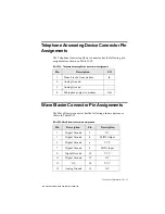
Страница 50: ... Table D 15 Wave Blaster connector pin assignments Table D 14 Telephone Answering Device connector pin assignments Pin Description I O 1 Mono Line In from modem In 2 Analog Ground 3 Analog Ground 4 Microphone output to modem Out Pin Description Pin Description 1 Digital Ground 2 NC 3 Digital Ground 4 MIDI Output 5 Digital Ground 6 VCC 7 Digital Ground 8 MIDI Input 9 Digital Ground 10 VCC 11 Digita...

Страница 51: ... 19 Analog Ground 20 Line In Right 21 Analog Ground 22 12 V 23 Analog Ground 24 Line In Left 25 Analog Ground 26 ResetB Pin Description Pin Description Table D 15 Wave Blaster connector pin assignments This manual downloaded from http www manualowl com ...

Страница 52: ...came about Information on the adapter card that conflicts with your card Hardware configuration information such as the base I O address IRQ line or DMA channel used Type and version of your operating system e g DOS 6 0 Windows 3 1x or Windows 95 Please ensure to retain your purchase receipt plus all packaging and contents until such time that all components of the product are functioning to your ...

Страница 53: ...s Inside Europe Through CompuServe By Fax Table E 1 Model and Serial Numbers of your hardware Hardware Model Number Serial Number Audio Card Video Card Fax Modem CD ROM Drive MIDI Device Telephony Card Others See label on underside of card Table E 2 Hardware Configuration Information Hardware Base I O Address IRQ DMA Audio Card Video Card Fax Modem CD ROM Drive MIDI Device Graphics Card Others Thi...

Страница 54: ...xes to common problems We will also welcome your recommendations and suggestions for new products and for improving our products in future releases See Creative Technical Services leaflet for details By Fax For fast and efficient Technical Support solutions please use our telephone service in the first instance If you decide to write or fax us then please send your correspondence ONLY to our Irela...

Страница 55: ...e is installed and working properly If not refer to the document that comes with your drive to solve the problem 2 Load the installation CD ROM into your CD ROM drive The installation CD ROM supports Windows 95 AutoPlay mode and starts running automatically 3 Choose the desired applications to install 4 Follow the instructions on the screen to finish installing your applications To install Real Au...

Страница 56: ... subnet mask This is usually not required as the Service Provider may automatically assign one to you each time you log on A dial up script This is required by some Internet Service Providers Your proxy server and port number This is required by some Internet Service Providers If you intend to use Microsoft Exchange to handle your e mail you would need the following additional information a Your e...

Страница 57: ...click Next 9 Enter the phone number to dial up your Internet Service Provider and click Next 10 Enter your user name and password and click Next 11 In the IP Address dialog box select My Internet Service Provider automatically assign me one and click Next 12 Enter the addresses for DNS Server and Alternate DNS Server The address is made of four numbers separated by periods e g 149 174 211 5 If you...

Страница 58: ...Select Windows Setup from the Title Bar d Select Have Disk Browse and locate the RNAPLUS INF file in ADMIN APPTOOLS DSCRIPT e Click OK and follow the instructions on screen to complete the installation 2 You will need a dial up script filename SCP in the directory Program Files Accessories of your system This is usually provided by your Internet Service Provider If you do not have a dial up script...

Страница 59: ... that your CD ROM drive is installed and working properly If not refer to the document that comes with your drive to solve the problem 2 Start Windows 3 Load the installation CD ROM into your CD ROM drive 4 Select Run from the File menu 5 Type the drive letter of your CD ROM drive eg D followed by the Internet directory the desired interneted audio application directory the operating system and th...

Страница 60: ...proxy server and port number This is required by some Internet Service Providers To set up Microsoft Internet Explorer you need to do the following Set up your modem under Windows 3 x and set up the Dialing and Internet Server Provider information To set up your modem under Windows 3 x and to set up the Dialing and Internet Server Provider information 1 Run your modem configuration software and en...

Страница 61: ...l be prompted to select whether you would like to use Microsoft Exchange to handle your Internet mail Select your choice fill in the necessary details and click Next 14 You will be prompted to select whether you want to set up an Internet News account Select your choice fill in the necessary details and click Next 15 Click Finish to complete the setup 16 Select the group you wish the icon for this...

Страница 62: ...P INI This file is in the Microsoft Internet Explorer installation directory which is IEXPLORE by default and you should change the COM3 or the COM4 section depending on which COM port your modem uses so that the interrupt line reads IRQ 10 or IRQ 11 again depending on the interrupt your modem uses Connecting to Your Internet Service Provider 1 Click Connect on the Connect to dialog box to dial yo...

Страница 63: ...k Parameters This information is very important If you enter erroneous data chances are your Creative Video Webphone will not operate properly Once you enter your User Information and Network Parameters press the CONFIGURE text located on top of the Configure window to save the information Entering your User Information Please enter all your User Information If it is inaccurate you will be misrepr...

Страница 64: ... mail address Then only the e mail address is protected i e other users can still configure their phones with whatever first and last names they desire You will not need to enter your password each time you use the Creative Video Webphone but you will need to enter your password if you reinstall the Creative Video Webphone for any reason so take care not to lose your password You may change your C...

Страница 65: ...SMTP Server used to send e mail from you to other users are both named mailhost which is used along with his provider s domain name to construct the POP and SMTP Server addresses mailhost provider net If you do not know or are not sure of the values for some of these parameters check your E Mail program s e g Eudora setup screen check your Web browser s e g Netscape setup screen or consult your In...

Страница 66: ...l using half duplex sound cards will never get an opportunity to talk they will always see LISTEN in their display and you will always see TALK in your display If this happens stop talking into the microphone and move the Voice Activation Level VOX slider to the right until the VOX meter displays Silence and you see the red bar Now verify the VOX enunciator displays Speaking and the red bar disapp...

Страница 67: ...rnet If this is the case try reconnecting to the Internet or call at another time 2 You cannot hear the remote party If Creative Video Webphone always displays TALK and never displays IN USE or LISTEN then you must raise your Voice Activation Level the VOX slider in the flip door so Creative Video Webphone can detect silence and allow the remote party to talk this is will not be the case if both y...

Страница 68: ...ot hear you the remote party s speaker volume is probably not set correctly Use the TXT button to launch the Text Board and tell raise their speaker volume For additional information see the NetSpeak home page at http www netspeak com No part of this publication may be reproduced or transmitted in any form or by any means without the prior written consent of Creative Technology Ltd Copyright 1997 ...

Страница 69: ...how you how to install and use CTCM and CTCU in your system We have also provided some information here from page 11 to page 16 to help you understand basic PnP concepts as well as Creative s PnP solution for non PnP environments And to find out how to solve some common PnP installation problems just flip to the last section which starts from page 16 The information here is organized into the foll...

Страница 70: ...installed CTCM This CTCM statement will be placed before all the statements that load other low level device drivers such as CTSB16 SYS and SBIDE SYS so that your Creative PnP cards will be configured before these device drivers try to use them If you add this line to CONFIG SYS manually please make sure that this line is placed after the statement if any that loads the other PnP configuration man...

Страница 71: ...nfigure a Creative PnP card again You can do so by running Creative PnP Configuration Manager CTCM from the DOS prompt 1 Exit to DOS if you are in Windows 3 1x 2 Change to the directory of your CTCM files The default directory is C SB16 3 Type CTCM and press ENTER CTCM will configure your Creative PnP card s and update the BLASTER environment variable if it detects a Creative audio card in your sy...

Страница 72: ...xisting legacy non PnP cards You have changed the resource settings of your legacy cards You have removed a legacy card from your system CTCU does not access the resource settings database used by Intel Configuration Manager ICM So do not use CTCU to change or disable your card settings if you already have ICM installed Use ISA Configuration Utility ICU instead For more details please refer to the...

Страница 73: ...s section You can use your mouse or keyboard to move around and select an item or action in CTCU Parameter Description S Notifies CTCU to run in silent mode This means that CTCU will not display any messages or screens It will simply update the parameters required by the Creative drivers If you do not use the S switch CTCU will run in full screen mode see Figure 1 W Informs CTCU to update the PnP ...

Страница 74: ...use this section to view the resource settings of the PnP cards in your system and change the settings of Creative PnP cards only When you select the PnP Cards section from the CTCU menu the Plug and Play window will appear listing the PnP cards in the system Choosing a card here will in turn display a list of logical devices on that particular card To view the resources for a PnP device double cl...

Страница 75: ...ng select one from the list Make sure it will not conflict with the other cards settings Then double click the new setting or click the OK button The Interrupt window displays the current interrupt resource setting and a list of possible settings To change this setting select one from the list Make sure that it will not conflict with the other cards settings Then double click the new setting or cl...

Страница 76: ...gure and test the settings again CTCU supports the testing of Creative s audio and wavetable devices only Legacy Cards Section You can use this section to enter view or change the resource settings of all the legacy non PnP cards in your system When you select the Legacy Cards section from the CTCU menu the Legacy window will appear displaying the resources taken up by the legacy cards in your sys...

Страница 77: ...acy Window Card Name Input Output Range I O Interrupt IRQ Direct Memory Access channel DMA 32 bit Memory Range Mem You must enter the card s name in the Card Name field The other fields can be left blank if the card does not use that resource s Remove Button Clicking this button in the Legacy window removes a selected card s settings from your system Once the settings are removed you can proceed t...

Страница 78: ...uld not be informed of resource s actually reserved by the legacy card This may in turn lead to resource conflicts System Devices Section You can use this section to view but not change the resource settings of the system devices in your computer When you select the System Devices section from the CTCU menu the System Device Resources window appears listing all the resources used by your system de...

Страница 79: ...st reserve some system resources such as input output address spaces interrupts Direct Memory Access channels or memory spaces for the card You must also make sure that there is no hardware conflict that is the resources reserved by one card are not used by another card in the same system Before Plug and Play PnP was introduced you can reserve system resources only by manually changing the setting...

Страница 80: ...lt older PnP systems shipped are not fully compliant with this specification So there are some compatibility problems For more details please read the section PnP in DOS Windows 3 1x on page 14 PnP System BIOS The PnP system BIOS is the lowest level of your PnP system Its main functions are to provide information on the resource settings of your system devices and to configure PnP cards Some PnP s...

Страница 81: ...tings of all your system devices and legacy cards configures PnP cards and provides relevant configuration information to other drivers or applications that access your PnP cards A PnP configuration utility allows you to view enter or change the resource settings of the PnP and legacy cards in your system The new or changed settings are then used by the PnP configuration driver to configure new Pn...

Страница 82: ...ach to PnP To solve problems similar to those mentioned in the previous section we have developed a DOS based PnP configuration driver and utility for the DOS Windows 3 1x environment They are called Creative PnP Configuration Manager CTCM and Creative PnP Configuration Utility CTCU CTCM can be loaded as a device driver through a statement in the CONFIG SYS file It can also be run from the DOS pro...

Страница 83: ...CU If you use a non PnP operating system like DOS Windows 3 1x and do not have a PnP BIOS or ICM your PnP card works like a software configurable card In such an environment CTCM needs to know which resources have been reserved by all the legacy and PnP cards and system devices in your system before it can allocate conflict free resources to your new Creative PnP card CTCM can get the resource set...

Страница 84: ... legacy non PnP cards and thus may give your PnP card some settings that would conflict with those of existing legacy cards ICM or other Configuration Manager Questions Question Must I remove ICM or another configuration manager in order to use CTCM Answer No you do not have to remove ICM or another configuration manager to use CTCM If both CTCM and ICM are installed in your system just make sure ...

Страница 85: ...n the hardware resource used by your legacy cards Next run CTCM to configure your PnP card Alternatively if you do not know your legacy cards settings use CTCU to change the settings of your PnP card Then run CTCM and test whether your card works properly This is a trial and error method since CTCM will not be informed about the resources that have been reserved by your legacy cards You may need t...

Страница 86: ...C dir EMM386 EXE other parameters where C dir is the directory in which your EMM386 program is installed and other parameters are the other parameters in the EMM386 statement No part of this publication may be reproduced or transmitted in any form or by any means without the prior written consent of Creative Technology Ltd Copyright 1997 by Creative Technology Ltd All rights reserved Version 2 0 O...

Страница 87: ...because currently the Sound Blaster hardware and driver do not support this While WaveSynth WG is playing a MIDI file you cannot enable Creative Mixer s LED display And vice versa Some of the constraints explained in this leaflet may not apply to your audio card For details refer to the Readme file in you audio package Full Duplex Mode When you select this mode you can play and record audio data c...

Страница 88: ...nnot play an audio file and record another one at the same time Creative FastSpeech playback is not supported Wave playback is restricted to the sampling rate conversions that Microsoft s Audio Compression Manager ACM supports ACM will do the necessary sampling rate conversion during playback Thus if you do not have ACM you cannot play 8 kHz wave files You cannot play wave files when Creative Mixe...

Страница 89: ...fault Also connects powered speakers and an external amplifier when built in amplifier is disabled Figure 1 Jacks and connectors on your audio card CD Audio connector Connects a CD ROM drive using a CD audio cable Joystick MIDI connector Connects a joystick or a MIDI device You can buy an optional MIDI kit that allows you to plug in the joystick and MIDI device simultaneously Telephone Answering D...

Страница 90: ...the possible default settings used by various devices on your card When necessary for example when there is a hardware conflict you may change one or more of these settings For more details see Appendix A Understanding the Installation in the Getting Started manual Table 1 Input Output I O addresses Device DefaultI OAddress Range Audio interface 220H to 22FH Game Joystick interface 201H MPU 401 UA...

Страница 91: ...ected To disable the effect clear the check box Enabling Disabling Full Duplex Operation The full duplex feature in your audio card is useful for audio conferencing and telephone like applications When enabled you can play back and record audio data at the same time You must however use the same sampling rate for both playback and recording To enable or disable full duplex in Windows 95 1 Click th...

Страница 92: ...elect Gameport Joystick 5 Click the Properties button 6 In the Properties dialog box If you have an Original Configuration Current check box To enable the interface make sure that the check box is selected To disable it clear the check box If you have a Disable In This Hardware Profile check box To enable the interface clear the check box To disable it make sure that the check box is selected 7 Cl...

Страница 93: ...ifier the built in amplifier must first be disabled To enable disable the built in amplifier 1 If your audio card is already installed switch off your system and all peripheral devices Remove the cover from your system and then the audio card 2 Enable or disable the built in amplifier according to the settings shown in Figure 2 Warning The built in stereo power amplifier can deliver a maximum outp...

Страница 94: ...r recording Volume Control Software volume control of Master Playback Volume Master Recording Volume Digitized Voice and inputs from MIDI devices CD Audio AUX Line In Microphone and PC Speaker Microphone level at 32 levels above 0 dB it is in 3 dB steps below 0 dB it is in 1 5 dB steps All other sources at 32 levels in 1 5 dB steps Full software control of fade in fade out and panning effects Buil...

Страница 95: ...nished under a license agreement and may be used or copied only in accordance with the terms of the license agreement It is against the law to copy the software on any other medium except as specifically allowed in the license agreement The licensee may make one copy of the software for backup purposes Sound Blaster is a registered trademark and Blaster is a trademark of Creative Technology Ltd In...

Отзывы: