19
5.4 TEST DI FUNZIONAMENTO
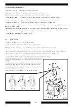
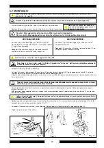
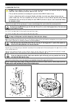
• Premendo il pedale (A), l'autocentrante (L) ruota in senso orario
• Spingendo verso l’alto il pedale (A) il piatto autocentrante (L) ruota in senso antiorario solo a bassa velocità
N.B:
Se il piatto girasse in senso opposto a quello indicato è necessario invertire due fili sulla spina trifase
• Premendo il pedale (U) si aziona lo stallonatore (R); rilasciando il pedale lo stallonatore ritorna nella posizione originale
• Premendo il pedale (V) si aprono le quattro griffe di bloccaggio (G); premendo nuovamente si chiudono.
• Premendo il pedale (H) si ribalta il palo(P); premendo nuovamente il palo ritorna in posizione di lavoro
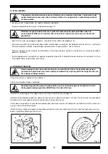
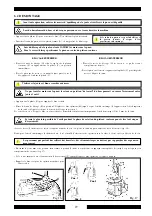
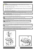
• Ponendo il pulsante di bloccaggio (K) in pos.1, si bloccano il braccio operante(M) ed il braccio orizzontale (N).
La torretta si posiziona automaticamente alla giusta distanza dal cerchio.
• Premendo il pulsante in pos. 2, i bracci si sbloccano e la torretta scende sul cerchio o fino all'altezza minima di servizio.
• Premendo il pulsante in pos. 3, i bracci si sbloccano e la torretta si alza in posizione di fuori lavoro
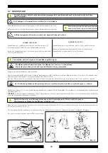
• Premendo il grilletto della pistoletta di gonfiaggio esce aria dalla testina.
5.4 OPERATING TESTS
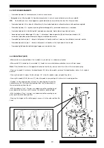
•When pedal (A) is pressed down, the turntable (L) should turn in a clockwise direction
•When pedal (A) is pulled up, the turntable (L) should turn in an anticlockwise direction only in with low speed.
Note:
If the turntable turns in the opposite direction to that shown, reverse two of the wires in the three-phase plug.
•Pressing the pedal (U) activates the bead breaker (R); when the pedal is released the bead breaker returns to its original
position.
•Pressing the pedal (V) opens the four clamps (G) ; when the pedal is pressed again they close.
•Pressing the pedal (H) tilts the arm (P); when the pedal is pressed again it returns to its working position.
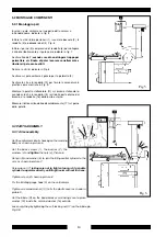
•Position 1 of the locking button (K) locks the mounting bar (N) and the
horizontal arm (M). The mounting head positions itself automatically at
the correct distance from the rim.
•With the button in Pos.2, the arms are unlocked and the mounting head
goes down onto the rim or until it reaches the minimum working height.
•With the button in Pos.3, the arms are unlocked and the mounting head
goes up to the out-of-work position.
•Pressing the trigger on the airline gauge causes air to be released from the
head.
Fig. 12
K
K
K
Pos. 1
Pos. 2
Pos. 3
Содержание CM 550
Страница 52: ...51 110V 1PH...
Страница 56: ...55...

