“DEPTH OF DRIVE ADJUSTMENT
The “DEPTH OF DRIVE ADJUSTMENT
flush with the work surface to shallow or deep countersink. First, set the air pressure for consistent
drive in the specific work as described above, then use the
the desired depth of drive.
TO ADJUST “DEPTH OF DRIVE ADJUSTMENT
1. With air pressure set, drive a few fasteners into a representative material sample to determine if
adjustment is necessary.
2. If adjustment is required, disconnect air supply.
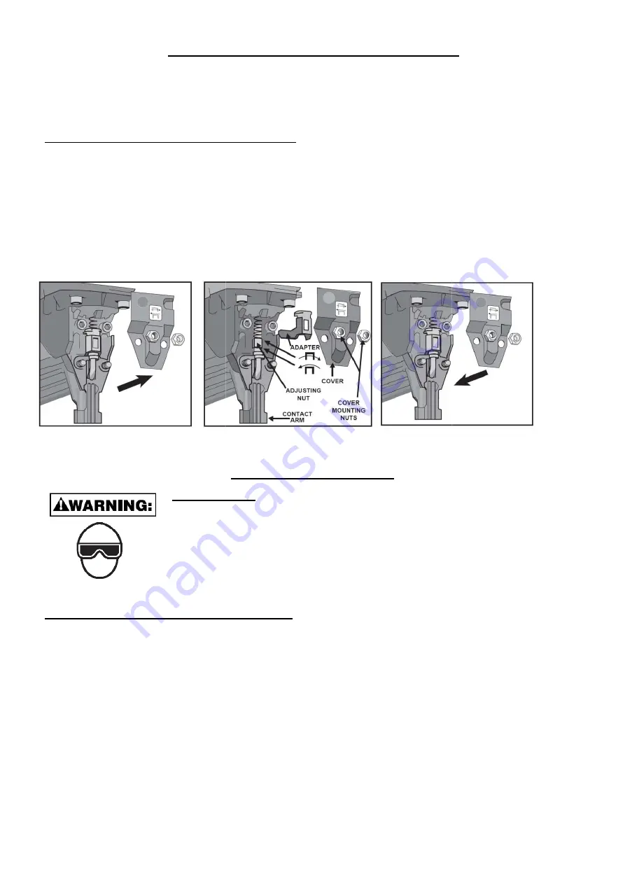
3. Refer to label on the outside of door for direction to turn adjusting nut. (See illustration)
4. Remove cover mounting nuts, cover and adapter. Observe the orientation of the flats on the
adjusting nut. Rotate the adjusting nut to the left to increase fastener dri
decrease it. Reorient the flats to be same as before. Reinstall adapter, cover and mounting nuts.
5. Before reconnecting air supply, check that trip mechanism parts operate freely with no binding or
sticking.
6. Reconnect air supply.
EYE PROTECTION
flying particles
the work area
protection is
injury.
The employer
equipment mus
frontal and side
provide adequate
BEFORE HANDLING OR OPERATING
READ AND UNDERS
REFER TO “TOOL
SYSTEM ON YOUR
There are four available systems on the
1. CONTACT TRIP OPERATION
4. REMOTE FIRE
DEPTH OF DRIVE ADJUSTMENT”
DEPTH OF DRIVE ADJUSTMENT” feature provides close control of the fastener drive d
flush with the work surface to shallow or deep countersink. First, set the air pressure for consistent
work as described above, then use the “DEPTH OF DRIVE ADJUSTMENT
DEPTH OF DRIVE ADJUSTMENT”:
With air pressure set, drive a few fasteners into a representative material sample to determine if
If adjustment is required, disconnect air supply.
to label on the outside of door for direction to turn adjusting nut. (See illustration)
Remove cover mounting nuts, cover and adapter. Observe the orientation of the flats on the
adjusting nut. Rotate the adjusting nut to the left to increase fastener drive depth, or to the r
the flats to be same as before. Reinstall adapter, cover and mounting nuts.
Before reconnecting air supply, check that trip mechanism parts operate freely with no binding or
TOOL OPERATION
PROTECTION which conforms to ANSI/ CE specifications and
particles both from the FRONT and SIDE should ALWAYS be worn
area when connecting to air supply, loading, operating
required to guard against flying fasteners and debris,
employer and/or user must ensure that proper eye protection
must conform to the requirements of the ANSI Z87.1 and 89/86/EEC,
side protection. NOTE: Non-side shielded spectacles
adequate protection.
TING THIS TOOL:
UNDERSTAND THE WARNINGS CONTAINED IN THIS
OOL SPECIFICATIONS” IN THIS MANUAL TO IDENTIFY
YOUR TOOL.
the pneumatic tool:
TION 2. SEQUENTIAL TRIP OPERATION 3. TRIGGER OPERATED
8
”
feature provides close control of the fastener drive depth; from
flush with the work surface to shallow or deep countersink. First, set the air pressure for consistent
DEPTH OF DRIVE ADJUSTMENT” to give
With air pressure set, drive a few fasteners into a representative material sample to determine if
to label on the outside of door for direction to turn adjusting nut. (See illustration)
Remove cover mounting nuts, cover and adapter. Observe the orientation of the flats on the
ve depth, or to the right to
the flats to be same as before. Reinstall adapter, cover and mounting nuts.
Before reconnecting air supply, check that trip mechanism parts operate freely with no binding or
and provides protection against
worn by the operator and others in
operating or servicing this tool. Eye
debris, which could cause severe eye
protection is worn. Eye protection
and 89/86/EEC, and provide both
spectacles and face shields alone do not
THIS MANUAL.
IDENTIFY THE OPERATING
3. TRIGGER OPERATED


