User and Maintenance Manual
Failsafe hydraulic brake ID 2000N
Model ID 2000N-116
Date: 2014/06/27
Revision: 1.1
www.coremo.it
Page
22
of
25
5.
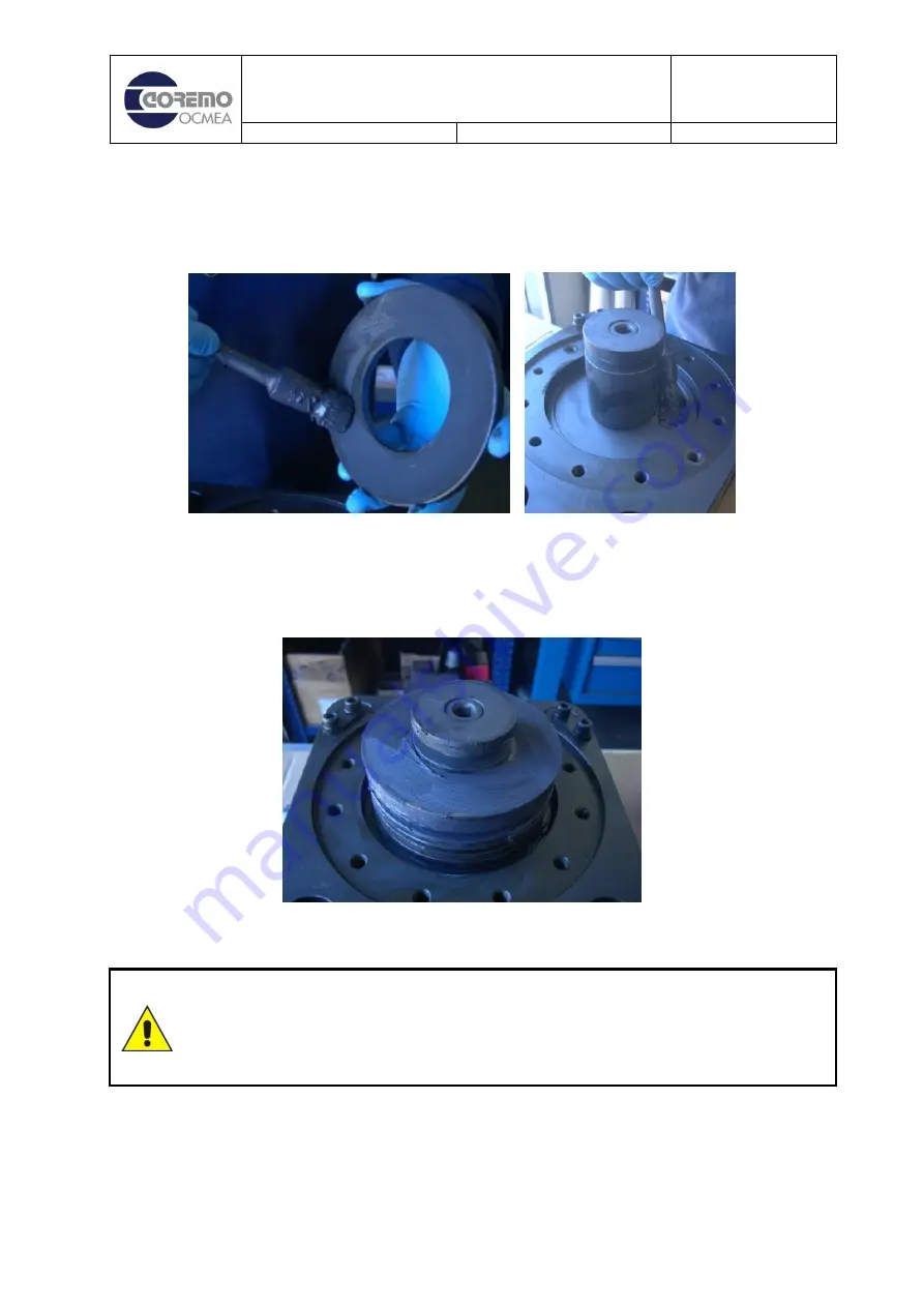
Lubricate the cup springs (Photo 39) and the part of the thruster in which they are housed
with copper paste MOLYguard COMPOUND RA/40 (or similar) (Photo 40), before
proceeding with reassembly.
Photo 39
Photo 40
6.
Insert in the thruster (D71243) the following parts in the following order: 1 shim C62295, 1
shim C62256, 6 cup springs C62410, 1 shim C62256 (Photo 41).
Photo 41
Position the cup springs correctly so that they do not affect the good operation of the
brake (Figure 3). Incorrect assembly will result in a tangential force different to what is
stated in this manual; the braking torque provided by the safety component will
consequently be different to what is desired and to the detriment of safety aspects.
7.
Put back the cover (D71242) on the brake body (E80834) using the screws (C61421)
complete with washers (C61321) (Photo 42). Tighten the M10 class 12.9 screws (C61452) in
a diagonal sequence with tightening torque 79 Nm (Photo 43).


