Cooper Industries Inc. Crouse-Hinds Division IF 1551
PO Box 4999, Rev 1 Syracuse, New York 13221 • U.S.A. New 01/08 Copyright© 2007, Cooper Industries, Inc.
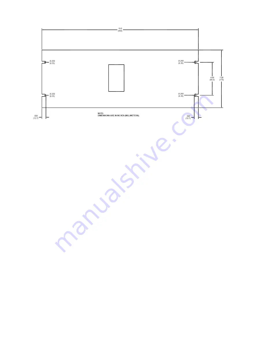
Figure 2-1 – CHC 140-1R Controller Mounting and Outline
Страница 1: ...rademarks and product names mentioned are properties of their respective companies and are recognized and acknowledged as such by Cooper Crouse Hinds Applicable Specifications This equipment meets or...
Страница 2: ...r While every effort has been made to ensure that the information in this manual is complete accurate and up to date Cooper Crouse Hinds assumes no liability for damages resulting from any errors or o...
Страница 3: ...itry while the equipment is operating Do not change components or make adjustments inside the equipment with power on Dangerous Voltages Can Persist with Power Disconnected Under certain conditions da...
Страница 4: ...hing Live Circuits 3 Dangerous Voltages Can Persist with Power Disconnected 3 Do Not Depend on Interlocks 3 Section 1 CHC 140 1 Controller Introduction and Operation 7 Controller 7 Options 7 Photocell...
Страница 5: ...oting 22 Troubleshooting Hints 22 Failing to Switch State in AUTO Mode 22 Erratic or Confused Tower or Structure Light Operation 22 Beacons 22 LED Displays 22 Checkout Procedure 24 Photocell Maintenan...
Страница 6: ...rs 12 Figure 1 3 Beacon Programming Switches 13 Figure 2 1 CHC 140 1R Controller Mounting and Outline 16 Figure 2 2 CHC 140 1W Controller Mounting and Outline 17 Figure 2 3 PEC 510 Photocell Mounting...
Страница 7: ...The CHC 140 1R fits in a standard 19 inch equipment rack System connections are made at a terminal block at the rear of the unit The CHC 140 1W is in an enclosure that allows the controller to be wall...
Страница 8: ...osition sets all the LEDs to green Fuses The F1 fuse is a 1 ampere fuse in the primary power circuit PCB100 Control Board Switches Display and Clear Buttons on PCB100 Green glowing LEDs correspond to...
Страница 9: ...L Cut to allow dual system operation it inhibits white light flashing at night A dual system is one that flashes only white lights during the day and flashes only red lights at night Dual systems may...
Страница 10: ...are observed to flash simultaneously This may cause some of the Tier and Beacon Display LEDs to temporarily switch to RED Failure Detection Monitoring provides an alarm if a beacon becomes inoperativ...
Страница 11: ...allowing you to manually synchronize with another system having its own independent controller Table 1 2 Front Panel Controls Fail Conf Display Switch Position Function FAIL Applies uniformly a fail s...
Страница 12: ...ON OFF ON DAYINHIBIT FAILCLOSE J507 1 1 1 1 1 1 1 6 6 6 6 6 2 2 PEC TWI PEC NITE GND CTRL MON SR SD ALARM COM ALARM NO GND 24V LOW 24V HIGH COM NO NC COM NO NC PEC ALARM DAY MODE TWI MODE NITE MODE N...
Страница 13: ...4999 Rev 1 Syracuse New York 13221 U S A New 01 08 Copyright 2007 Cooper Industries Inc FRONT OF UNIT TIERS ON OFF BEACON 1 BEACON 2 BEACON 3 BEACON 4 ON OFF ON OFF OFF ON 1 2 3 4 5 7 6 SECTION OF PCB...
Страница 14: ...oper performance Place the unit at an adequate distance from a powerful RF radiator Controller Wiring Figure 2 5 shows the controller and photocell wiring in a typical installation Only general inform...
Страница 15: ...tocell Be certain that these connections are correct before applying power otherwise equipment damage will result See Figure 2 6 Installation Checklist Controller Checklist Consult the installation dr...
Страница 16: ...Cooper Industries Inc Crouse Hinds Division IF 1551 PO Box 4999 Rev 1 Syracuse New York 13221 U S A New 01 08 Copyright 2007 Cooper Industries Inc Figure 2 1 CHC 140 1R Controller Mounting and Outline...
Страница 17: ...Cooper Industries Inc Crouse Hinds Division IF 1551 PO Box 4999 Rev 1 Syracuse New York 13221 U S A New 01 08 Copyright 2007 Cooper Industries Inc Figure 2 2 CHC 140 1W Controller Mounting and Outline...
Страница 18: ...New York 13221 U S A New 01 08 Copyright 2007 Cooper Industries Inc 0 33 8 38 2 275 57 8 2 58 65 5 0 125 3 175 HEX 1 0 25 4 3 06 77 7 1 2 NPT 0 10 2 54 NOTE ALL DIMENSIONS ARE IN INCHES MILLIMETERS 1...
Страница 19: ...Cooper Industries Inc Crouse Hinds Division IF 1551 PO Box 4999 Rev 1 Syracuse New York 13221 U S A New 01 08 Copyright 2007 Cooper Industries Inc Figure 2 4 CHC 140 1 Panel Connections...
Страница 20: ...Cooper Industries Inc Crouse Hinds Division IF 1551 PO Box 4999 Rev 1 Syracuse New York 13221 U S A New 01 08 Copyright 2007 Cooper Industries Inc Figure 2 5 Typical Installation Wiring...
Страница 21: ...Cooper Industries Inc Crouse Hinds Division IF 1551 PO Box 4999 Rev 1 Syracuse New York 13221 U S A New 01 08 Copyright 2007 Cooper Industries Inc Figure 2 6 CHC 140 Internal Wiring...
Страница 22: ...led to switch state If possible swap the photocell with one known to be operative Switch the Mode Selector Switch through the manual modes and see if the structure lights follow the intensity indicate...
Страница 23: ...ies Inc Crouse Hinds Division IF 1551 PO Box 4999 Rev 1 Syracuse New York 13221 U S A New 01 08 Copyright 2007 Cooper Industries Inc Table 3 1 Major Troubleshooting Symptoms Table 3 1 Major Troublesho...
Страница 24: ...UTO Perform the remaining steps with the CONTROL and MONITOR wires attached for normal operation and verify that the programming switches see Programming on Page 1 2 are set correctly 7 All LED indica...
Страница 25: ...Use a nut driver Take care to prevent scratching the paint while removing the nuts 4 Behind the front panel remove the four screws holding the display panel board to the front panel Replacement Revers...
Страница 26: ...Industries Inc Section 4 Recommended Spare Replaceable Parts Customer Service Customer Service 1 866 764 5454 Shipping Address Cooper Crouse Hinds Wolf 7th North Street Syracuse NY 13208 Ordering Par...
Страница 27: ...oper Industries Inc Crouse Hinds Division IF 1551 PO Box 4999 Rev 1 Syracuse New York 13221 U S A New 01 08 Copyright 2007 Cooper Industries Inc Figure 4 1 CHC 140R System Controller Component Locatio...
Страница 28: ...oper Industries Inc Crouse Hinds Division IF 1551 PO Box 4999 Rev 1 Syracuse New York 13221 U S A New 01 08 Copyright 2007 Cooper Industries Inc Figure 4 2 CHC 140W System Controller Component Locatio...
Страница 29: ...ator Site Owner provide all that apply owner agent or subcontractor Contractor Name Contractor Company Point of Contact Information Name Phone Number Email Address Fax Number and Cell Phone or alterna...
Страница 30: ...will be issued to the customer for the new product 5 After receiving the Cooper Crouse Hinds RMA number please adhere to the following packaging guidelines All returned products should be packaged in...