background image

6-25

Assembly Manual: Tube

Revised 12.2019

Fig 214 - Logo

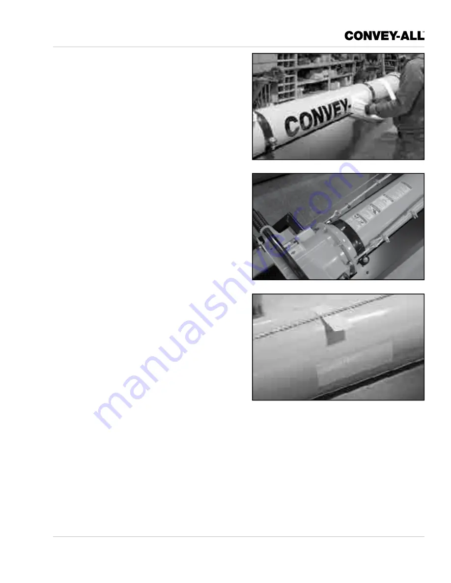
6.7.4  Apply Decals, Logos and Reflectors:

Review  the  assembly  drawing  supplied,  to 
determine the location of all decals, logos and 
reflectors.

110. Be  sure  the  application  area  is  clean  and

dry.  Ensure  the  surrounding  temperature  is
above 10°C (50°F).
- Remove  all  dirt,  grease,  wax  from  the

surface.

- Clean with a non-ammonia based cleaner.
- Wipe  the  clean  surface  with  isopropyl

alcohol on paper towel, and allow to dry.

111. Determine  the  exact  position  before  you

remove the backing paper.

112. Peel a small portion of the split backing paper.

113. Align the decal over the specified area. Use

a  squeegee  to  carefully  press  the  small
portion, with the exposed adhesive backing,
into place.

114. Slowly  peel  back  the  remaining  paper  and

carefully  smooth  the  rest  of  the  decal  into
place.

115. Small air pockets can be pierced with a pin

and smoothed out using the squeegee, or a
piece of sign backing paper.

116. Apply amber reflector strips:

- To each side of the hopper and discharge.
- In  equal  intervals  of  less  than  15  feet  up

the tube.

117. Apply a red reflector strip to the end of the

discharge spout.

Fig 215 - Decals

Fig 216 - Amber Reflectors

Содержание 1640-TL

Страница 1: ...TRUCK LOAD CONVEYOR 1640 TL 1650 TL 1658 TL ASSEMBLY MANUAL...

Страница 2: ...y addressed as follows Convey All Industries Inc 130 Canada Street Winkler Manitoba R6W 0J3 Canada This warranty shall expire one 1 year after the date of delivery of the new machinery If these condit...

Страница 3: ...ON 3 1 3 1 Tools 3 1 3 2 Receiving 3 2 3 3 Prepare for Assembly 3 2 Section 4 ENGINE CRADLE ASSEMBLY 4 1 4 1 Battery 4 1 4 2 Gas Engine 4 2 4 3 Diesel Engine 4 6 4 4 Fuel Tank 4 8 4 5 Hydraulic Oil Re...

Страница 4: ...charge Spout 6 19 6 6 1 Stainless Steel Discharge Components 6 20 6 7 Complete the Tube 6 21 6 7 1 Install Windguards 6 21 6 7 2 Install Drip Pan 6 23 6 7 3 Run Electrical Wires 6 23 6 7 4 Attach Deca...

Страница 5: ...Gather all the required tools and supplied Have hoists forklifts cranes or other lifting devices with the required lifting capacity available for use Have stands on hand They must have sufficient cap...

Страница 6: ...1 2 Assembly Manual 1600 TL Series Conveyor Revised 12 2019 This page intentionally left blank...

Страница 7: ...injury or death Indicates a hazardous situation that if not avoided will result in death or serious injury This signal word is limited to the most extreme situations Typically for machine components w...

Страница 8: ...SAFE workers It is their responsibility to understand all Safety and Assembly instructions in this document and to follow them An untrained worker exposes himself and bystanders to possible serious in...

Страница 9: ...over a lifetime without hope of natural recovery Clear working area of stones branches or hidden obstacles that might be hooked or snagged causing injury or damage Assemble only in daylight or good ar...

Страница 10: ...remaining paper and carefully smooth the rest of the decal into place 6 Small air pockets can be pierced with a pin and smoothed out using the squeegee or a piece of sign backing paper 2 6 HYDRAULIC...

Страница 11: ...rate engine with grass leaves dirt or other combustible materials in muffler area Do not operate engine without muffler Do not tamper with governor springs governor links or other parts which may incr...

Страница 12: ...formation on the maximum cold tire pressure PSI Keep the tires inflated to this setting 2 9 BATTERY SAFETY Keep all sparks and flames away from batteries as gas given off by electrolyte is explosive A...

Страница 13: ...gathering lift equipment stands and tools 3 1 TOOLS Tool requirements include but are not limited to IMPORTANT Always use calibrated torque wrenches Use of anti seize lubricant dirt in hole and damag...

Страница 14: ...hat all listed parts and supplies have been included in the crate and accompanying packages 5 Contact the transport company and the factory immediately if any components or bags are missing 3 3 PREPAR...

Страница 15: ...ands must hold 2500 lb in weight and be stable 4 1 BATTERY 1 Place a layer of rubber belting onto the base of the holder 2 Assemble the brackets on the battery holder which is in the middle of the cra...

Страница 16: ...5 Drill 4 holes for engine mounting bolts EQUIPMENT WEIGHT HAZARD Use lift equipment rated to hold 2000 lb 6 Hoist engine and position over predrilled holes Tighten the bolts to secure the engine int...

Страница 17: ...at the base of the engine 12 Attach the black ground battery cable over top the ground and tighten the bolt 13 Fit the battery cables onto the battery 14 Add a cable clamp to the cradle frame to secur...

Страница 18: ...C SEALANT HAZARD Never use Teflon tape to seal threads It does not hold at high pressure Always use Loctite 545 Thread Sealant Note Refer to schematic for specifics on the hydraulic fittings 18 Slide...

Страница 19: ...12 2019 Fig 18 Hydraulic pump Fig 19 Close pump window 23 Inside window sandwich the spider between coupler and pump Tighten set screw 24 Drill a hole into the top of the base Clean up the metal shav...

Страница 20: ...x 4 3 DIESEL ENGINE If you will be using a diesel engine on your conveyor the model of engine can vary widely These instructions are meant as a general guide only Note The engine sits on brackets with...

Страница 21: ...27 Throttle cable 28 Plug the cable from the engine into the back of the control box 29 Attach the throttle to the bent plate on the front edge of the valve mount plate Note Hydraulic valves will be i...

Страница 22: ...lange Rear bottom centre flange 36 Insert the appropriate fittings into each port For unit with gas engine Coat 2 threaded metal plugs with teflon thread sealant Insert plugs into front centre and top...

Страница 23: ...ervoir Add Loctite 545 thread sealant 40 Install filler cap Place cork gasket around hole on top of reservoir Place wire mesh filter over cork Add a second cork gasket over the filter place the base o...

Страница 24: ...plugs back in place 45 Remove plugs from back of reservoir 46 Insert an oil return fitting in the left side upper flange Use Loctite 545 Thread Sealant Note When installed the spout of the Pump Inlet...

Страница 25: ...c filter Use a 1 25 x 6 25 inch hose between the filter and 90 fitting into the reservoir 50 Connect the filter assembly to the return fitting at the left side of the reservoir 51 Bolt the filter moun...

Страница 26: ...fuel pump Fuel Hose to Diesel Engine 59 Run two fuel hoses from tank to engine The first from the rear centre is the supply hose the second from the side front corner is the return hose 60 Zip tie th...

Страница 27: ...64 Bolt a hydraulic bi directional relief valve to the bottom of the valve mount support arm The ports are numbered which will be referenced when installing the hoses 65 Install the correct fittings...

Страница 28: ...82 82 Fig 51 Valve Drawing 72 70 Send a 3 4 x 82 inch hose from the filter fitting to return port on the conveyor belt valve 71 Run a 3 4 x 72 inch hose T fitting before the filter to return port on t...

Страница 29: ...77 Route a 3 4 x 34 inch hose from the right inner port on the pump to the far right supply port on the conveyor belt valve 78 Run a 1 2 x 25 inch hose from the right outer port on the pump to the 45...

Страница 30: ...gine Cradle Revised 12 2019 4 8 FINISH CRADLE 80 Screw handles onto the valves 81 Adhere the decals in their locations Valve Instructions Gas Only Diesel Only Hydraulic Oil Only No Smoking Fig 58 Valv...

Страница 31: ...ENT WEIGHT HAZARD Use lift equipment rated to hold 2000 lb Never lift heavy objects alone find help 1 Place the axle on stands 2 Lay undercarriage main frame tubes in position against brackets on axle...

Страница 32: ...ds 7 Put 3 1 2 inch Pulley into the bracket Insert the pin and secure with a cotter pin 8 Hoist cradle onto the undercarriage 9 Attach cradle to mount Use 5 8 x 1 3 4 inch bolts Sandwich one washer be...

Страница 33: ...t from the inside All other bolts are placed from the outside 13 Mover Kit Axle Hydraulic Motor Mount Coat both ends with lubricant Bolt into place above axle extending away from the engine Use 1 2 x...

Страница 34: ...outside 15 Mover Kit Over Centre Linkage Use 1 2 x 2 1 2 inch bolt Bolt to the Handle The welded rod must be on the lower portion of component pointing inward Insert the bolt from the outside 18 Lower...

Страница 35: ...for the axle Remove plugs Add 4 90 hydraulic fittings point to the rear 23 Bolt motors onto motor mounts Use 5 16 x 1 1 4 inch bolts 24 Rotate the motor shafts so key grooves are to the top 25 Add spr...

Страница 36: ...s to the left side of the cushion block which will sit in the axle as well 30 Run a 1 2 x 15 inch hose from the right side of the cushion block to the bottom outside fitting on the motor 31 Run a 1 2...

Страница 37: ...NDERCARRIAGE LIFT ARMS 34 Bolt on wheels 35 Lower axle to sit wheels on the ground 36 Attach Lift Arms to hinge bracket on Undercarriage Main Frame Tubes Use 5 8 x 2 1 2 inch bolts Do not tighten yet...

Страница 38: ...Tighten these bolts 40 Lift the cylinder with a hoist Attach the base of cylinder to cross tube bracket Use 1 2 x 1 1 2 inch bolts Do not tighten yet 41 Attach Hydraulic Lift Upper Mount Clamp Plate...

Страница 39: ...bolt holes Fig 91 Route the 66 inch hose Fig 93 Ball valve 54 Fig 92 Fittings to the hydraulic cylinder 5 3 3 Hydraulic Cylinder Hoses 46 Prepare hydraulic fittings for placement on lower plug on cyl...

Страница 40: ...end of Lift Arms 54 Slide the bearing assembly over the roller slide shaft on both ends Centre the shaft Secure with 5 16 x 2 inch carriage bolts Place from the inside Washers and nuts tightened from...

Страница 41: ...Cable 57 Feed a 3 8 x 31 cable through top of cylinder assembly around the left side pulley 58 Return cable back under cylinder Up and around the lower left side pulley Thread it through the space in...

Страница 42: ...just before the mounting plate 62 Bring the cable back around the support Thread it back through the three clamps IMPORTANT Apply U Bolt over dead end of cable live end rests in saddle Tighten nuts ev...

Страница 43: ...he correct measurement IMPORTANT These measurements are necessary to fasten the cable at the correct length 68 Add three cable clamps to the other end of the cable Feed the cable around the pulley fro...

Страница 44: ...the cylinder into the centre of the frame Insert the 3 4 x 3 1 2 inch clevis pin 77 Position the end of the 1 1 2 x 6 inch hydraulic cylinder in the mount at the centre of the axle Insert the 3 4 x 3...

Страница 45: ...then tighten the nuts 84 Insert the lift cylinder 2 x 24 between main frame and steering axle assembly Insert 1 x 3 1 2 inch clevis pins into steering frame Secure with cotter pins Insert 1 x 4 1 2 in...

Страница 46: ...ed to the main frame later in the assembly 91 Run both hoses along the main frame tube and up to the mover kit valves Attach the 80 inch hose to the right outer rear port Attach the 76 inch hose to th...

Страница 47: ...ock 97 Now clamp the lift cylinder hoses on top of the clamp block Fig 125 Clamp the hoses Fig 126 Red rear reflector on axle Fig 127 Document holder 100 Fasten the document holder on the inside of th...

Страница 48: ...5 18 Assembly Manual Undercarriage Revised 12 2019 This page intentionally left blank...

Страница 49: ...16 x 2 inch carriage bolts Place the bolts from the inside Add washers outside and tighten the nuts 2 Place eccentric locking rings off centre fit over the shaft outside the bearings on both ends of t...

Страница 50: ...two 20 tubes 1658 TL two 20 and one 7 1 2 tube IMPORTANT The flange seam marks the top of tube Tubes have male and female ends Point male ends towards the discharge 5 Find the tube flange seam place i...

Страница 51: ...7 9 10 9 6 0 2 10 4 101 4 7 4 9 61 2 13 3 16 103 4 28 1 81 18 20 0 2 10 4 7 4 9 61 2 13 3 16 103 4 28 1 32 7 37 2 41 11 2 44 6 79 79 79 80 62 67 85 80 79 15 81 19 13 0 2 10 4 10 1 4 7 4 9 6 1 2 13 3 1...

Страница 52: ...ETURN ROLLER FL TYPE 1 7 8 x 17 7 8 x 7 8 3 10 501118 RETURN ROLLER 1 875 x 17 875 x 438 5 11 405705 TUBE CLAMP TYPE 2 W WIND GUARD MOUNT 1 13 405482 WINCH MOUNT TUBE CLAMP 1 14 403938 ROLLER SLIDE TY...

Страница 53: ...ten yet EQUIPMENT WEIGHT HAZARD Use lift equipment rated to hold 2000 lb Ensure stands can hold the weight and are stable OVERHEAD EQUIPMENT HAZARD Use caution when working under the tube 15 Lift the...

Страница 54: ...roller 18 Fit the Heavy Duty Return Roller under the tube before the Drive Box Fasten a 6 inch tube clamp over the tube Do not tighten the bolts Note Roller should already be installed If not attach...

Страница 55: ...he end of the unit Refer to Figures 139 140 or 141 Do not tighten bolts yet 6 2 2 Level Components IMPORTANT Conveyor ends must be level before all other components can be levelled 23 Level Hopper and...

Страница 56: ...fter IMPORTANT There should be 1 16 inch 1 5mm spacing between roller and bracket leg Use rubber mallet to bend setting spacing 27 Place the Flanged Return Rollers To the Return Roller Bracket after t...

Страница 57: ...L is 107 feet long Belt for the 1658 TL is 122 feet long 35 Thread the belt over the return rollers and hang at the end of the discharge Fig 156 Conveyor belt roll Fig 157 Belt at discharge Tube 36 Fi...

Страница 58: ...hopper 43 Feed the belt around the top roller and onto the hopper bed 44 Pull it across the hopper bed 45 Feed it around the hopper tail roller Fig 160 Lead belt lead under transition Fig 161 Belt ar...

Страница 59: ...emblies over the roller slide shaft on both ends Centre the shaft Secure with 5 16 x 2 inch carriage bolts Place the bolts from the inside Add washers outside and tighten the nuts 48 Place eccentric l...

Страница 60: ...the heavy duty return roller 52 Feed the belt into the Drive Box Pull it below and around the first roller 53 Thread the belt over and around the large drive roller then back inside 54 Guide the belt...

Страница 61: ...belt corners at both ends of the lacing IMPORTANT Taper the belt corners so they don t catch when running 62 Set the adjustment bolts on the tail roller to 3 inch 77mm Set both sides equally so the b...

Страница 62: ...to the flange Bolt the cross brace Level the cross brace Tighten bolts Place the cable clamps on top of the cross brace 65 Add thimbles to cable eye bolts 66 Attach eye bolts to the open holes at the...

Страница 63: ...Live end b rests in saddle Tighten nuts evenly alternate from one nut to other until recommended torque is reached 72 Push the first clamp up against the thimble at the eyebolt Tighten the clamp Move...

Страница 64: ...eye bolts Leave as much adjustment capacity at the hopper end It can be easily reached for future adjustments 79 Tighten hopper eye bolts until five threads go through the nut Tighten the eye bolt loc...

Страница 65: ...Note If curved tighten cable on outside of arc or loosen cable on inside of arc 83 Sight along the side of tube to confirm it has a slight upward bow in it Tighten cable with the discharge end eye bo...

Страница 66: ...er 1 4 to 1 2 inch Then re tension at the drive box Alignment The belt is properly aligned when it rotates in the centre of the rollers Check it at the discharge roller hopper rollers and in the drive...

Страница 67: ...Note There are six positioning slots on the top of the Discharge Spout Manually position the spout at the particular output angle depending on your needs 86 Swing the spout up and bolt it to the hood...

Страница 68: ...of the metal housing 90 If an electric actuator is included Install the electric actuator mount bracket across the spout Install the bracket to the top of the housing 91 Bolt the Discharge Spout to t...

Страница 69: ...cut to fit 60 inch windguard after Discharge guard 100 inch windguard to Slide 90 inch windguard after Slide 30 inch tapered windguard to Drive Box 65 5 16 inch guard between Drive Box and Hopper 1658...

Страница 70: ...pping screws to secure windguards to each roller bracket and the edge of the slide 98 Position next windguard below Roller Slide Cut out a piece of the top corner edge of guard to fit when overlapping...

Страница 71: ...hts and actuator package a wiring harness is included 103 Connect the coloured wires on the electric actuator to the corresponding colours in the 16 gauge roll of wire Encase wire connection in condui...

Страница 72: ...nchoring wire down to the light bracket above the Drive Box 108 Attach the hopper work light onto its bracket above the drive box Connect its wires a 3 foot piece of 2 conductor wire Wrap in conduit 1...

Страница 73: ...position before you remove the backing paper 112 Peel a small portion of the split backing paper 113 Align the decal over the specified area Use a squeegee to carefully press the small portion with th...

Страница 74: ...firm the tub straight side to side Note If curved tighten cable on outside of arc or loosen cable on inside of arc 119 Sight along the side of tube to confirm that it is straight Tighten or loosen cab...

Страница 75: ...aware of tension on the spring when the Hopper Hoop is in place Sudden release of hoop will cause injury Note The hopper hoop has a downward bend in it Thread the canvas onto the hoop with the stitch...

Страница 76: ...the hoop arms will angle down 5 Insert hoop ends over each end of the Mount Bar 6 Insert the cotter pin to hold the hoop in place Bend the cotter pins to secure them HIGH SPRING TENSION Tension is add...

Страница 77: ...des Note The end of the Insert with the screw hole closest to the end goes in first Now the holes will match the pre drilled holes on the side bracket 12 Centre the Tail Canvas Insert inside the front...

Страница 78: ...to the transition Fit Flashing around the belt which is wrapping around roller It must tightly cup the belt Corner Flashing lays beneath Side Flashing Flashing 23 Lay corner flashing underneath side f...

Страница 79: ...opper canvas to access the hoop inside Work a cable thimble around the hoop tube inside the canvas 31 Thread the cable through a swage String the cable around the thimble inside the canvas Insert the...

Страница 80: ...7 6 Assembly Manual Hopper Revised 12 2019 Fig 239 Rubber tubing Fig 240 Finished open transition hopper 36 Work rubber tubing over the canvas frame to protect the canvas edges The hopper is complete...

Страница 81: ...e undercarriage in position below the tube 3 Lower the tube so the Roller Slide sits in the roller at the top of the undercarriage Keep most weight supported by the winch Fig 241 Move undercarriage be...

Страница 82: ...riage roller inside Use 1 4 x 1 inch 6 3 x 25 4 mm bolts Bolt one on lower end of Slide Use 2 bolts on upper side 6 Fasten other the angle Iron for the opposite side of the Slide 7 Position the Underc...

Страница 83: ...ve box 12 Bolt the Levelling Arm bracket to the cradle frame below the engine 13 Fasten one end to the Arm Mount Tab Use 3 8 x 1 1 4 inch bolts Use 3 washers one on either end of the bolt and one betw...

Страница 84: ...ned free from the Drive Box until now 15 The windguards can now secured to Drive Box Use self tapping screws Attach the guard to the front and back of the Drive Box 16 Repeat on the other side Fig 252...

Страница 85: ...ched under the cradle or rub against the wheel 19 Finish clamping the two hoses along the undercarriage arms Note Where possible use existing screws holding windguards 20 Add a clamp block on top of t...

Страница 86: ...over into place to cover and protect the hose valve connections If your conveyor includes the optional lights and actuator package a wiring harness with the control box is included The lights and disc...

Страница 87: ...tics essential for the assembly process For information not included here or for a digital copy of this manual please call your dealer or Convey All Industries Inc directly for assistance 1 800 418 94...

Страница 88: ...5 33 63 45 M5 6 4 9 7 7 16 41 30 72 53 100 75 M6 10 7 15 11 1 2 61 45 110 80 155 115 M8 25 18 35 26 9 16 95 60 155 115 220 165 M10 50 37 70 52 5 8 128 95 215 160 305 220 M12 90 66 125 92 3 4 225 165 3...

Страница 89: ...800 418 9461 www convey all com conveyors convey all com 2019 Convey All Industries Inc Registered Trademarks Used Under License Printed in Canada 12 2019 Part No 650507345 REV6...

Отзывы: