35
ACCESSORIES & OPTIONS
ACCESSORI ES
31
1. To install the anti-tip tube, align the tube with the end of the round frame tubing
located next to the rear wheel.
Fig. 120
2. Push the detent pin while positioning the anti-tip tube onto the round frame tubing, and then
push until the “release button” pops through the hole located on the anti-tip tube.
Fig. 121
3. Repeat steps 1 & 2 for opposite side.
Fig. 122
4. To remove the anti-tip tubes, perform 1-3 steps in reverse order.
Anti-Tip Tubes
Fig. 120
Fig. 121
Fig. 122
1. Engage caster lock by pushing the caster lock down.
Fig. 119
2. To disengage the caster lock, push the bottom
portion of caster lock.
Fig. 119
Push down to
engage Caster
Lock
Push here to
disengage
Caster Lock
Fig. 119
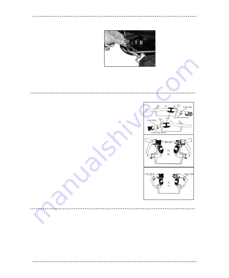
1. Thread the 3-Bar Slide onto the strap with the curved side down. Feed the strap through the
molded strap slot. If you have the padded version, thread the Pad onto the strap as shown
Fig. 116
2. Thread the strap end through the Buckle.
Fig. 117
3. Thread the strap end through the 3-Bar Slide.
Fig. 118
Shoe Holders
Fig. 116
Fig. 117
Fig. 118
Caster Locks
Shoe Holders
1. Thread the 3-Bar Slide onto the
strap with the curved side down.
Feed the strap through the molded
strap slot. If you have the padded
version, thread the Pad onto the
strap as shown.
FIG.89
2. Thread the strap end through the
Buckle.
FIG.90
3. Thread the strap end through the
3-Bar Slide.
FIG.91
FIG.89
FIG.90
FIG.91
CONVAI D USER’S GUI DE
30
LTV Vent Holder
1. Align male dovetail bracket located on
ventilator with female dovetail bracket
located on frame.
Fig. 111
2. Slide down and lock securely
into bracket.
Fig. 112
3. Attached Ventilator.
Fig. 113
Utility Bag
The Utility Bag attaches to the back of
the chair, but can be removed and
converted to a tote bag.
Fig. 114
To attach:
1. Hook clasps onto straps.
Caution: Do not overload bag.
Legrest Extension
1. Place your hand on the push
button located at the knee joint.
Fig. 109
2. Depress the push button to adjust lower
extremity to design angle and release
button.
Fig. 110
Fig. 109
Fig. 110
Fig. 114
Pommel
1. Loosen knob.
2. Fully insert pommel into
designated slot at the front center of
the seat pan.
Fig. 108
3. Tighten knob.
Fig. 107
Fig. 107
Fig. 108
WARNING:
Do not use the LTV Holder when using a soft back on the Trekker Back Canes
!
Fig. 111
Fig. 112
Fig. 113
Male
dovetail
Female
dovetail
Fig. 115
Utility Bag
The Utility Bag attaches to the back of
the chair, but can be removed and
converted to a tote bag.
FIG.88
To attach:
1. Hook clasps onto straps.
Caution: Do not overload bag.
button located at the knee joint.
Caution: Do not overload bag.
FIG.88
Extended Strap Vest (Butterfly Harness)
1. Stand behind user and pullfinger loops to adjust top straps.
2. Pull finger loops to adjust bottom.
Содержание YoYo
Страница 14: ...CONVAID USER S GUIDE 14 Trekker Seating Module...


