


UD52 User Guide
Issue code: 52nu3
18
40
3.27
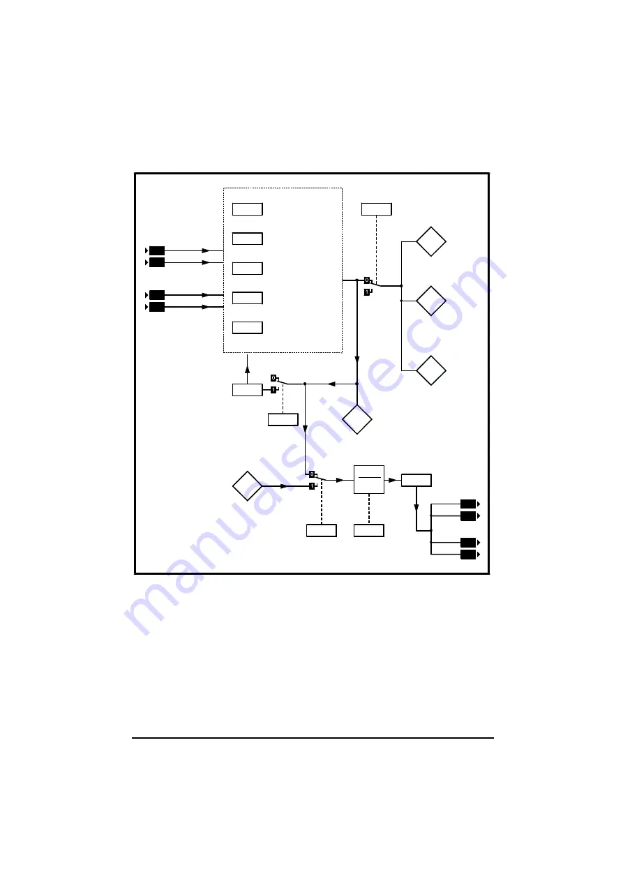
Encoder 1
position
16.06
Simulated-encoder
output
select
16.12
SIN-COS encoder
−
No. of lines per
revolution
16.13
SIN-COS encoder
−
No. of revolutions
16.14
SIN-COS as
reference encoder
16.15
SIN-COS encoder
voltage
select
41
42
43
SININ
SINREF
COSIN
COSREF
16.09
SIN-COS encoder
phase offset
16.10
SIN-COS encoder
phasing test
16.11
SIN-COS encoder
update
disable
16.03
SIN-COS encoder
revolution count
16.04
SIN-COS encoder
incremental
position (coarse)
16.05
SIN-COS encoder
incremental
position (fine)
16.07
Simulated-encoder
output scaling
1
2
[16.07]
16.08
Simulated encoder
F/D output enable
50
51
53
54
A (f)
A\ (f\)
B (D)
B\ (D\)
16.02
SIN-COS encoder
RPM
16.16
SIN-COS encoder
−
serial comms. disable
Figure 5 Logic diagram for the UD52
Содержание UD52
Страница 4: ...UD52 User Guide Issue code 52nu3 ...
Страница 11: ...UD52 User Guide Issue code 52nu3 7 Figure 1 Installing the UD52 in the Unidrive ...
Страница 28: ...UD52 User Guide Issue code 52nu3 24 ...
Страница 34: ...UD52 User Guide Issue code 52nu3 B 4 ...
Страница 36: ...UD52 User Guide Issue code 52nu3 C 2 ...


