background image

  Set the Computer Network 


CPSA-PCB100 Reference Manual 


  22 


1.


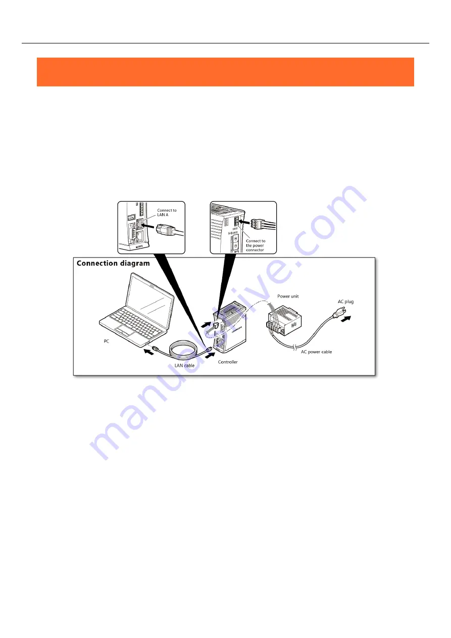
Connect with the PC 

To set the product, you need to first set up the network between the PC and the product in order to 
establish communication. 
First, connect the product with the PC. 


1


Follow the instructions below to connect the PC, the controller, and the power unit. 


*  Refer to 

“Power Cable (page 98)”

 for how to create a power cable. 


2


Connect the power unit with AC plug, then turn on the PC. 


*  After connecting the power unit with AC plug, it takes a few minutes for the controller to 

complete the start-up. (approx. 1-2 min) 


Содержание CONPROSYS Alpha Series

Страница 1: ...up CPSA PCB100 Introduction 5 Safety Precautions 13 Set the Computer Network 21 CONPROSYS WEB Setting 31 PLC Backup 47 Product Nomenclature and Function 77 Installation 85 Troubleshooting 100 Appendix...

Страница 2: ...arning 20 1 Information security risks 20 2 Security measures e g 20 Set the Computer Network 21 1 Connect with the PC 22 2 Set the PC Network 23 1 PC Network Setting Procedure for Windows 10 23 3 Che...

Страница 3: ...ttery 69 4 Configure Schedule Setup 70 4 Monitor 71 1 Configure Backup 71 2 Configure Manually Backup 72 3 Configure Restore 73 5 Monitor Failure Diagnosis 74 1 Check Failure Diagnosis Page 74 6 Monit...

Страница 4: ...Power 98 2 LAN 99 3 RS 232C 99 4 Digital Input 99 5 Digital Output 99 Troubleshooting 100 1 Troubleshooting 101 1 In general 101 Appendix 103 1 Specifications 104 1 Specifications 104 2 Power Requirem...

Страница 5: ...5 Introduction This section provides necessary information of the product such as the outline bundled items and manuals before actual use...

Страница 6: ...ves the programs and the configured data as well as the parameters of PLC used in a control device so that they can be restored easily when the system fails It supports the PLCs of the most major manu...

Страница 7: ...tures flexibility in installation Adaptable to a temperature range between 20 and 60 C The product is capable of operating in the temperature between 20 and 60 C It can be installed in the various env...

Страница 8: ...cense 1 attached on the side of the product This product is verified in conformity with our recommended power supply In case you use other power supplies thus it may not be able to fulfil certificatio...

Страница 9: ...et up with CONPROSYS WEB Setting Refer to page 23 Set up the network of PC Refer to page 32 Set Username and Password Refer to page 37 Save the settings Refer to page 41 Set up the system Refer to pag...

Страница 10: ...de Must read this after opening the package This lists the product configuration and describes the precautions Included in the package Printed matter Reference Manual Read this when setting up the CON...

Страница 11: ...such as calculation and control as well as on CONPROSYS HMI for operating and editing the monitoring screen through the Online Help Consult the Online Help as necessary CONPROSYS VTC Visual Task Contr...

Страница 12: ...visit our website to check the version of firmware and update to the latest one if necessary Updating firmware to the latest version will resolve troubles and stabilize the operation Download https w...

Страница 13: ...13 Safety Precautions Understand the following definitions and precautions to use the product safely Never fail to read them before using the product...

Страница 14: ...tand the meanings of these labels to operate the equipment safely DANGER DANGER indicates an imminently hazardous situation which if not avoided will result in death or serious injury WARNING WARNING...

Страница 15: ...r medical equipment or other applications that require a very high level of reliability Do not use the product in such applications If using the product in applications where safety is critical such a...

Страница 16: ...e event of failure or abnormality foul smells or excessive heat generation unplug the power cables immediately and contact your retailer To connect with peripherals use a grounded shielded cable To cl...

Страница 17: ...enclosure having enough strength Disconnection between the product and the module during the operation may result in damage To prevent the disconnection always mount both of them on DIN rail for opera...

Страница 18: ...cordance with the instruction manual may cause harmful interference to radio communications Operation of this equipment in a residential area is likely to cause harmful interference in which case the...

Страница 19: ...ors at their end of life should be disposed separately from the household waste If a chemical symbol is printed beneath the symbol mark shown above it indicates that the battery or accumulator contain...

Страница 20: ...tended operations 2 Security measures e g Do not keep using the default password Refer to the product manual for the password setting Set a strong password Combined with upper and lowercase letters an...

Страница 21: ...21 Set the Computer Network This section describes how to connect the product with a PC set the network and to check the communication...

Страница 22: ...ish communication First connect the product with the PC 1 Follow the instructions below to connect the PC the controller and the power unit Refer to Power Cable page 98 for how to create a power cable...

Страница 23: ...o make the IP addresses as shown The product must set a unique IP address for the bold part 200 or 101 that is not used by other devices on your network If proxy is set to your PC do not use the proxy...

Страница 24: ...Network CPSA PCB100 Reference Manual 24 3 Double click the appeared Ethernet 4 Click the Property in Ethernet Status dialog box 5 Double click the Internet protocol version 4 TCP IPv4 in Ethernet Prop...

Страница 25: ...k CPSA PCB100 Reference Manual 25 6 In the Internet protocol version 4 TCP IPv4 property set IP address and Subnet mask as shown below 7 Click the OK the OK the Close to close the dialog box and compl...

Страница 26: ...er them and click the OK Refer to Compatible Web Browser page 32 for details of compatible web browser For an actual operation change User name and Password in User name and Password from the Maintena...

Страница 27: ...the controller and the power unit Refer to Power Cable page 98 on how to make power cable CAUTION When connecting the product with PLC through HUB LAN cable a straight through cable relies on HUB Whe...

Страница 28: ...serial communication module CPS COM 2PD configurable type is necessary in order to add the function 2 After adding the CPS COM 2PD to the product connect the twisted pair cable with the shield to the...

Страница 29: ...2PD Pin Number Signal Name Description 1 GND Signal ground 2 RxD Received data 3 RxD Received data 4 TxD Transmitted data 5 TxD Transmitted data Full duplex Setting Data Transfer Mode Setting Full Dup...

Страница 30: ...loop if there are RTS and CTS and use the terminator in accordance with the PLC as well As for setting baud rate parity and stopbits the setting values of PLC communication should match the setting v...

Страница 31: ...31 CONPROSYS WEB Setting This chapter describes the product system and functions...

Страница 32: ...lems may arise due to the use of incompatible browser Be sure to use the web browser that is compatible 2 Start up CONPROSYS WEB Setting Start the Web browser on your computer that is connected with t...

Страница 33: ...00 Reference Manual 33 3 CONPROSYS WEB Setting Basic Operation CONPROSYS WEB Setting Page Structure Click the menu item on the left side of the screen This opens a page to set the details of the menu...

Страница 34: ...not use this function Otherwise it could result in operating failures Save setting Do not use this function Otherwise it could result in operating failures Initialize setting Restore all the settings...

Страница 35: ...k setting Set up IP address of the product and check network communications Networks can be set for LAN A and LAN B respectively Select Select how to set IP address Static Set up IP address and Subnet...

Страница 36: ...bled when Static IP is selected Default LAN A 255 0 0 0 LAN B 255 255 255 0 Default gateway Set up IP address of default gateway It is enabled when Static IP is selected Leave it blank when this is no...

Страница 37: ...setting and make your own password User Name Password Add or delete a user to log in CONPROSYS WEB Setting through a Web browser Enter user name and password using 1 to 31 letters of one byte alphanu...

Страница 38: ...By clicking reload time is updated from the synchronization server By clicking write the current time is written to ROM Synchronization server Set the address of NTP server when using NTP Setting FQDN...

Страница 39: ...9 Change the time zone setting to UTC and use the product Change data and time When setting date and time manually enter date and time in the field then update Setting 1970 01 01 00 00 00 2038 1 19 03...

Страница 40: ...CONPROSYS WEB Setting CPSA PCB100 Reference Manual 40 5 Backup setting Do not use this function 6 Restore setting Do not use this function...

Страница 41: ...ents set in CONPROSYS WEB Setting to ROM Click the save to ROM PWR LED starts flashing and saving begins CAUTION Do not turn off the power until PWR LED flashing has stopped approx five seconds Withou...

Страница 42: ...etting Initialize all of the settings to their factory defaults Click the initialize to initialize the settings Perform the Save setting and the Reboot to enable the initialized settings 9 System info...

Страница 43: ...are version Serial number Display the serial number ID Display the required ID to register in CDS or CDS2 of cloud server MAC address Display MAC address of wired LAN Run time version Display the run...

Страница 44: ...the latest communication log from the server specified as the data transfer URL Azure log Show the latest sending data log to Azure IoT Hub NTP server communication log Show the latest communication l...

Страница 45: ...View to display the license information of the software The approval is required to use the software 10 Reboot Shutdown This reboots or shuts down the product Select reboot or shutdown and then click...

Страница 46: ...ite Download https www contec com download From the Browse button specify the firmware and click the Upload button The file is compressed by ZIP format Decompress it and use the bin file extension CAU...

Страница 47: ...47 PLC Backup This section describes PLC Backup menu and each of the setting procedure...

Страница 48: ...1 1 101 viewer view htm pagepath SD PAGE Menu Page layer 0 in the address bar then press the enter on your keyboard The dialog box asking for the User name and Password appears enter them and click t...

Страница 49: ...49 2 Setup Menu System Setup The system setup allows you to select a connecting PLC type and to set a battery replacement cycle Click the Edit button to move to the edit page and click the Menu button...

Страница 50: ...process Message Display the process result Return button Return to the System Setup page Setup Battery Replacement Cycle See below to set up the battery replacement cycle Item Display Input Descriptio...

Страница 51: ...munication Setup Set up the details of PLCs in the PLC communication Click the Edit button to move to the edit page and click the Menu button to return to the Menu Setup PLC Communication See below to...

Страница 52: ...rial Parity Display Serial parity that is currently set Serial Data Bit Display Serial data bit that is currently set Input Value Enable Disable Input Enabled or disabled to be changed Name Input PLC...

Страница 53: ...s currently set Program Enable Disable Display Program enable disable that is currently set Program Size Display Program size that is currently set Input Value Area 1 3 Enable Disable Input Area enabl...

Страница 54: ...l 54 Item Display Input Description PLC Switch button Switch to the selected PLC setup Page Switch button Switch to the selected page Register button Execute the registration process Return button Ret...

Страница 55: ...d address that is currently set Program Parameter Enable Disable Display Program Parameter backup enable disable that is currently set Input Value Area 1 3 Enable Disable Input Area enable disable to...

Страница 56: ...PLC Backup CPSA PCB100 Reference Manual 56 Item Display Input Description Register button Execute the registration process Return button Return to the PLC Communication Setup page...

Страница 57: ...3 End Address Display Area end address that is currently set Input Value Area 1 3 Enable Disable Input Area enable disable to be backed up Area 1 3 Device Type Input Device Type to be backed up Refer...

Страница 58: ...acement Day Display Battery replacement day that is currently set Input Value Battery Replacement Day Input Battery replacement day year month day to be replaced Message Display Display the process re...

Страница 59: ...CPSA PCB100 Reference Manual 59 Schedule Setup The schedule setup allows you to schedule the backup Click the Edit button to move to the edit page and click the Menu button to return to the Menu Edit...

Страница 60: ...ntly set Execution Cycle Display Backup execution cycle day that is currently set Daily 1 Max 999 days Time Display Execution time hour minute that is currently set Input Value Schedule Enable Disable...

Страница 61: ...u Monitor The monitor allows you to set the Battery Replace Recommendation Day the Backup History and the Manually Backup and Restore Click Display Update to update the backup information of PLCs and...

Страница 62: ...ange Display Display the presence or absence of change Display Update button Update the display contents Menu button Return to the Menu Manually Backup Setup See below to set up the manually backup It...

Страница 63: ...t Value currently set PLC type is displayed 4 Enter the setting day of battery replacement cycle in the Battery Replacement Cycle Input Value 5 Number of selected PLC type is displayed in the PLC Type...

Страница 64: ...product from PLC type 5 Number of selected PLC type is displayed in the PLC Type Input Value 6 Click the Register button to confirm the selected PLC type 7 When the settings have been confirmed the me...

Страница 65: ...mation Page Switch Basic 3 In the Basic page you need to enter the PLC basic information corresponding to the number of PLCs to be connected 4 In Current Value the PLC basic information currently set...

Страница 66: ...d if you click the PLC Switch 1 5 button Page Switch Basic Area Battery button or Return button and go back to the previous page before confirming the settings by clicking the Register button Also bea...

Страница 67: ...e Switch Area 3 In Area page you need to enter the Area information corresponding to the number of PLCs to be connected 4 In Current Value the PLC area information currently set is displayed 5 Enter t...

Страница 68: ...d if you click the PLC Switch 1 5 button Page Switch Basic Area Battery button or Return button and go back to the previous page before confirming the settings by clicking the Register button Also bea...

Страница 69: ...nt Value the PLC and the Battery Replacement Day currently set are displayed 5 Enter the battery replacement day in Input Value in accordance with PLC 6 Click the Register button to confirm the inform...

Страница 70: ...page to set the PLC backup 3 In Schedule page you need to enter the Schedule information corresponding to the number of PLCs to be connected 4 In Current Value the backup schedule currently set is dis...

Страница 71: ...tart Web browser 2 From PLC Backup menu select Monitor The figure below appears 3 PLC Information and Backup History of five PLCs are displayed in 1 5 respectively 4 If you wish to update the PLC info...

Страница 72: ...Monitor The figure below appears 3 Select PLC you wish to back up manually from PLC 1 to PLC 5 The green line is displayed under the button of the PLC number you selected 4 Click the Backup to start t...

Страница 73: ...y1 4 in PLC 1to PLC5 The selected PLC number is displayed in the PLC field and the selected generation number is displayed in the Restore number Also the green line is displayed under the button of th...

Страница 74: ...Page 1 Refer to PLC Backup menu Page47 to start Web browser 2 From PLC Backup menu select Failure Diagnosis The figure below appears 3 Diagnosis State of each PLC is displayed in 1 5 respectively The...

Страница 75: ...Backup menu Page47 to start Web browser 2 From PLC Backup menu select Error History The figure below appears 3 Click Display Update button to update the list of error history 4 Page indicates the cur...

Страница 76: ...ackup menu Page47 to start Web browser 2 From PLC Backup menu select Operation History The figure below appears 3 Click Display Update button to update the list of operation history 4 Page indicates t...

Страница 77: ...77 Product Nomenclature and Function This section describes product component names and their functions pin assignment of each connector...

Страница 78: ...tor included in the package 4 LED Indicator 1 This indicates status of the product 5 Rotary Switch For both H and L of ID use with the setting 00 6 Digital I O Connector Do not use it 7 LAN Port This...

Страница 79: ...N Never set or remove the product while power is active Always confirm the PWR LED is turned off before setting or removing the devices 2 Maintenance Connector Do not use this Maintenance purpose only...

Страница 80: ...D flash while updating such as firmware ERR Red ON It lights up when error occurs OFF It indicates the system runs normally DIO0 DIO3 Green ON It lights up at the time of I O OFF It indicates there is...

Страница 81: ...d Function CPSA PCB100 Reference Manual 81 5 Rotary Switch For both H and L of ID use with the setting 00 6 Digital Input Digital Output Connector Reserved 8 0 7 F 6 E 5 D 4 C 3 B 2 A 1 9 8 0 7 F 6 E...

Страница 82: ...s left unconnected 5 N C This pin is left unconnected 6 RX Reception data input 7 N C This pin is left unconnected 8 N C This pin is left unconnected Color and Description LED Color Display Descriptio...

Страница 83: ...is set to OFF Do not use this 9 Power Switch It controls the power supply Pin Assignment Operation Description Press it for a short time To turn off the power Press it for a while To restart the prod...

Страница 84: ...The baud rate that can be used for PLC Backup is 4 800 bps 19 200bps Pin Assignment Pin No Signal Name Direction Description 1 CD Input Carrier detection 2 RD Input Reception data 3 TD Output Transmis...

Страница 85: ...85 Installation This section describes how to mount the product on a DIN rail and to connect to an external device with a cable...

Страница 86: ...tall the Product 1 Installation Conditions Installation Orientation Install the product in the orientations shown below 0 C Other orientations may cause problems such as malfunctions due to inadequate...

Страница 87: ...just the air current to make certain that the temperatures measured in the points stay within the specified temperature 20 60 C Controller alone Controller and module s 50mm 50mm 50mm Front Side 50mm...

Страница 88: ...may occur if there is other device generating high heat the radiation will influence the product to increase its temperature Do not install this product into the fully sealed space except the case in...

Страница 89: ...or removing cables using the switches or transferring the products Disconnection between the product and the module or between the modules during the operation can result in damages To prevent the di...

Страница 90: ...lation CPSA PCB100 Reference Manual 90 3 Push the hook up to lock the product on the DIN rail How to Remove 1 Pull down the hook to unlock If the hook is stuck use a slotted screwdriver to unlock Fixe...

Страница 91: ...than 4 5mm into a hole see the figure below By using the screwdriver as leverage move it upward in the direction of the arrow to unlock By rotating the screwdriver Place the slotted screwdriver the po...

Страница 92: ...ff before setting or removing the modules Always check the module is firmly fixed on DIN rail with hooks when setting the product How to Set 1 First slide the attached end cover to remove it from the...

Страница 93: ...side rail of the controller or another module that is already mounted When the rails fit slide the setting module all the way toward the DIN rail 4 Fix and secure the module on the DIN rail by locking...

Страница 94: ...unlock Unlock the hooks with a slotted screwdriver There are two ways to unlock the hooks using a slotted screwdriver Unlock them by one of the following methods Using the screwdriver as leverage Inse...

Страница 95: ...g the screwdriver Place the slotted screwdriver the point should be smaller than 8mm as shown in the figure Rotate the screwdriver 90 degree in either direction 3 With the hooks unlocked pull the modu...

Страница 96: ...ly 7mm plus or minus 0 5mm of the covered part of a cable and insert it to the opening 2 After the insertion secure the stripped part by turning screws with a slotted driver to prevent it from disconn...

Страница 97: ...rt it to the opening 2 After the insertion secure the stripped part by turning screws with a slotted driver to prevent it from disconnecting CAUTION Removing the connector plug by grasping the cable c...

Страница 98: ...This product is designed to operate at least with 30 90 watt power supply In addition the power supply must fulfill the following requirements Rising time for up to 24V 2 milliseconds up to 30 millis...

Страница 99: ...etc Check the requirements of the external device and select either a straight through or crossed null modem cable as appropriate If special treatment of the signal lines in the connector is required...

Страница 100: ...100 Troubleshooting This section describes how to solve the troubles when the product does not function properly...

Страница 101: ...the network port Use the ping command from a host computer and see whether the server unit responds Ping the IP address of the server unit The server unit should respond if it is operating Example Th...

Страница 102: ...your user name or and password you can restore the default factory settings by turning on the power to the product with SW1 2 on left The default factory settings of IP address can also be restored C...

Страница 103: ...103 Appendix This section lists the specifications and the physical dimensions of the product and the details of model name...

Страница 104: ...4pprox Scan Time 74 sec at 20000 steps Hardware Specifications Item Description CPU ARM Cortex A8 600MHz Memory On Board 512MB DDR3 SDRAM ROM On Board 32MB NOR Flash for OS LAN Transmission standard 1...

Страница 105: ...output Output isolation Semiconductor relay isolation Output voltage resistance 1000V The number of output signal channels 4 usable as digital input or digital output Maximum output voltage current 13...

Страница 106: ...ticles Not to be excessive Corrosive gases None Line noise resistance Line noise AC Line 2kV 4 Signal Line 1kV IEC61000 4 4 Level 3 EN61000 4 4 Level 3 Static electricity resistance Touch 4kV IEC61000...

Страница 107: ...C Q series Parameter Program Configured data backup available MELSEC FX series Configured data backup available PLC by JTEKT PC10G series Configured data backup available Communication method Ethernet...

Страница 108: ...olation transformer a noise cut transformer Never bundle place nearby or in parallel the power supply cable and the input output signal lines If lightning surge protection is required connect the surg...

Страница 109: ...Appendix CPSA PCB100 Reference Manual 109 2 Physical Dimensions mm 94 7 5 1 44 7 124 8 14 Open Lock 4 18...

Страница 110: ...Description Type Lithium primary battery Model BR2330A HD Maker Panasonic Nominal Voltage 3V Nominal Volume 255mAh 2 How to remove the battery When disposing of the product follow the instruction belo...

Страница 111: ...3 Unhook the five tabs of the product to remove the body cover 4 Cut the two holding metals with nippers and take off the battery CAUTION When disposing of the battery please comply with your local mu...

Страница 112: ...fore setting up Program 0 76777 The available program capacity differs depending on the capacity of extended memory Make sure to check it before setting up JW 30H series by SHARP Item Backup Range LAN...

Страница 113: ...ile number and data range differ depending on the PLC model number Make sure to check it before setting up Program Cannot be backed up Serial connection File 0 Cannot be backed up File 1 99 0 177777 T...

Страница 114: ...t the program capacity parameter type settings 1 1 Parameter should be already installed into CPU by system tool mfd By Mitsubishi Electric to restore program parameter CPU needs to be reset once afte...

Страница 115: ...ries by JTEKT Item Backup Range LAN connection D1 D3 0 FFF U0 U3 0 7FFF EB0 EB7 0 7FFF The available data capacity differs depending on CPU version Make sure to check the backup range before setting u...

Страница 116: ...Description DIN rail fitting power supply CPS PWD 90AW24 01 Fitting power supply 90W Input 100 240VDC Output 24VDC 3 8 A CPS PWD 30AW24 01 Fitting power supply 30W Input 100 240VDC Output 24VDC 1 3 A...

Страница 117: ...117 Customer Support and Inquiry CONTEC provides the following support services for you to use CONTEC products more efficiently and comfortably...

Страница 118: ...seful information including product manuals that can be downloaded through the CONTEC website Download https www contec com download You can download updated driver software firmware and differential...

Страница 119: ...119 Index...

Страница 120: ...Index CPSA PCB100 Reference Manual 120 Revision History MONTH YEAR Summary of Changes December 2018 The First Edition April 2019 The supported PLCs were increased...

Страница 121: ...ka 555 0025 Japan https www contec com No part of this document may be copied or reproduced in any form by any means without prior written consent of CONTEC CO LTD CPSA PCB100 Reference Manual NA06530...

Отзывы: