background image

14

In st ru c t io n  m an u al 

C o n e r g y   IP G   s t r in g   in v e r t e r   s e r ie s

3   P r o d u c t   d e s c r ip t io n

E

N

G

L

IS

H

Solar power system 

(1)

You can connect up to two photovoltaic module strings
(photovoltaic modules connected in series) to each string
inverter of the Conergy IPG series. If you wish to connect
more strings, use the Multi-Contact branch connector plugs
and sockets. Note the specifications on the string inverter
(see chapter 9.1, page 57).

Check whether the desired string configuration complies with
the voltage and current ranges of your inverter.

Safety system

In general, a photovoltaic system does not affect the risk of a
lightning strike on the building; apart from the solar power
system with a roof structure which stands out and is a more
likely strike point. In such cases a lightning conductor system
must be installed. Discuss this with a specialist, who will be
pleased to help you with the selection and installation of a
lightning conductor system. 

Regardless of whether or not the photovoltaic system has a
lightning conductor system, the solar power system must be
earthed. Among other things, the earthing provides
protection of persons.

DC wiring

(2)

Connect the solar power system modules with one another
using solar wiring. Solar wiring generally consists of single-
pole cables with double insulation. They are UV and weather-
resistant. Conergy recommends the use of sheathed cables.
This type of cable can also be used to connect the module to
the string inverter of the Conergy IPG series. 

When choosing the cables, check what cable section can be
connected to the connection boxes of your module. The
section varies from 2.5 to 6.0 mm

2

. Connect the solar cables

to the string inverter using 

Multi-Contact

 MC4 connector

plugs and sockets. 

DC disconnect 

(3)

Before working on the inverter, and also in the case of fire,
the device must always be disconnected from the solar
power system. To disconnect, actuate the DC disconnect (DC
power circuit breaker). The circuit breaker must be capable of
switching the DC rated current of the solar power system
under full load. 

Inverter 

(4)

The question of what inverter types you should install
depends both on the system size and the local
circumstances. With the help of the Conergy IPG sizer
system planning program (see www.conergy.com) you can
determine the optimum combination of solar power system
and Conergy inverters.

Содержание IPG 4000

Страница 1: ...Conergy IPG string inverter series Operating manual ...

Страница 2: ...nical directives 6 2 Sa fe t y 9 2 1 Intended use 9 2 2 Responsibilities of the owner operator 9 2 3 Basic safety instructions 10 2 4 Warnings 11 3 Pr o d u c t d e s c r ip t io n 13 3 1 General information on photovoltaic systems 13 3 2 Block diagram 15 3 3 Functions 17 4 C o n e r g y IPG s t r in g v is io n in v e r t e r s e r ie s 19 5 Tr a n s p o r t a n d in s t a lla t io n 2 5 5 1 Incl...

Страница 3: ... 4 Connecting the mains cable 36 6 5 Connecting the solar system 40 6 6 Connecting the Conergy SunReader 44 6 7 Connecting the 230 V power supply 45 6 8 Connecting Easyconnect 45 6 9 Connecting further string inverters 46 6 10 Connecting the terminator 46 6 11 Commissioning 47 7 Tr o u b le s h o o t in g 4 9 7 1 LED indicator fault messages 50 7 2 Fault warnings on the display 52 8 Re m o v a l 5...

Страница 4: ...rless units for single phase power feed to the grid This instruction manual relates to the string inverters of the Conergy IPG series Conergy IPG 4000 vision string inverter Conergy IPG 4000 string inverter Conergy IPG 5000 vision string inverter Conergy IPG 5000 string inverter The designation vision represents the product version with a display The number represents the performance level corresp...

Страница 5: ...sconnection String inverters of the Conergy IPG series can also optimally be used with the internet based Conergy SunReader monitoring system If you have already opted for the Conergy IPG easyconnect generator junction box Conergy has already integrated the Conergy SunReader into the individual monitoring system components With the help of the Conergy IPG sizer system dimensioning program you can ...

Страница 6: ...e form 1 and 2 Display messages are shown in a di f f er ent f ont The names of companies other than Conergy are shown in italics Symbols 1 5 Environmental information The Conergy IPG series string inverters are made from materials almost all of which can be used again through raw materials recycling The device its accessories and its packaging should therefore be recycled in an environmentally re...

Страница 7: ...gnetic compatibility amended by 93 97 EEC 73 23 EEC Council Directive on the approximation of the laws of Member States relating to electrical equipment for use within certain voltage limits amended by 93 68 EEC Electromagnetic Compatibility EMC Generic standards Immunity for industrial environments IEC 61000 6 2 1999 mod German version EN 61000 6 2 2001 Electromagnetic Compatibility EMC Generic s...

Страница 8: ...IEC 62109 2 2005 Information technology equipment Safety Part 1 General requirements IEC 60950 1 2005 12 Automatic disconnection device between a generator and the public low voltage grid DIN VDE 0126 1 1 Guidelines of the VDEW German Electricity Association governing the parallel operation of in plant generating systems with the low voltage grid of the power supply company Please note that the ab...

Страница 9: ...8 Instruction m anual C o n e r g y IPG s t r in g in v e r t e r s e r ie s 1 In t r o d u c t io n ENGLISH ...

Страница 10: ...ual and displayed on the device The specialist electrician employed by the owner operator must observe and follow all the safety instructions specified in this instruction manual Prior to assembling installing commissioning and removing an Conergy IPG string inverter series inverter the electrician must have read and understood this instruction manual in full Conversion work on Conergy AG equipmen...

Страница 11: ...s A second person must be present during all work on live system parts and leads In the event of an unforeseen electrical accident that person must be able to switch off the power supply and provide aid Damage due to improper transportation When slewing and depositing the load electronic equipment can be damaged by the force of impact During transportation electronic equipment can be damaged by te...

Страница 12: ...nces of disregarding the risk Instructions on what to do to avert the risk and prevent injuries or damage to property The indicator word on the warning signs denotes one of the following risk levels DANGER Denotes a major extraordinary risk from electrical current failure to observe which could lead to serious injury or death WARNING Denotes a potentially dangerous situation which may lead to seri...

Страница 13: ...12 Instruction m anuall C o n e r g y IPG s t r in g in v e r t e r s e r ie s 2 Sa fe t y ENGLISH ...

Страница 14: ...ected photovoltaic system essentially consists of the following components Solar power system 1 The solar power system consists of several photovoltaic modules connected in sequence or in parallel Safety system DC wiring 2 DC disconnect 3 Inverter 4 AC wiring AC disconnect 5 Meter cabinet with circuit allocation consumption and feed in meter and house connection 6 Fig 3 1 House with photovoltaic s...

Страница 15: ...be earthed Among other things the earthing provides protection of persons DC wiring 2 Connect the solar power system modules with one another using solar wiring Solar wiring generally consists of single pole cables with double insulation They are UV and weather resistant Conergy recommends the use of sheathed cables This type of cable can also be used to connect the module to the string inverter o...

Страница 16: ... the inverter to the low voltage mains For systems with AC output up to 4 6 kW a single inverter is generally used For the operation of systems with higher outputs several string inverters are used and connected in several phases 3 2 Block diagram Fig 3 2 Schematic block diagram The electrical energy of the solar power system is conducted via a sheathed filter The filter prevents the penetration o...

Страница 17: ... fault current monitoring For safety reasons every photovoltaic system must be disconnected from the public power grid in various circumstances such as mains interruption For this reason the string inverters of the Conergy IPG series monitor the public power grid by means of the phase shifting process Every string inverter has the following data interfaces CTRL to the Conergy IPG easyconnect excha...

Страница 18: ... the string inverters of the Conergy IPG series as transformerless inverters in photovoltaic systems with special photovoltaic modules such as thin film modules Maximum Power Point You increase the yield of your photovoltaic system by optimum tuning of the string inverter to the photovoltaic modules Your system will reach its optimum level of efficiency when it is working at the Maximum Power Poin...

Страница 19: ...nverters of the Conergy IPG string inverter series monitor the grid using the phase shifting process Phase Shifting If there is a fault of the public power grid each string inverter of the Conergy IPG series detects this fault on the basis of the change in frequency of the current The frequency of the public grid is at 50 Hz nominal frequency The digital control system of the string inverters of t...

Страница 20: ...rned to the status and output screen In order to be able to operate the display at any time of the day or night Conergy recommends the connection of an external 230 V power supply If you have chosen combination with the Conergy IPG easyconnect generator junction box you will not need an external power supply as this is already integrated in the generator junction box The string inverters of the Co...

Страница 21: ...ISH Language You can call up the display text in German English Italian or Spanish 2 Confirm your selection by touching OK Decide whether you want to choose the language every time an inverter is commissioned 3 Confirm your selection by touching the button Yes or No Selecting the language 1 Select the desired language by touching the relevant button ...

Страница 22: ...g the language Display You can call up updated data for today the values from the previous day and photovoltaic system data for the last 7 days via the display The default setting displays current status and yield If you want to see the values for the previous day or the data for the last 7 days select the Di agr ammenu and then the desired display Pr evi ous day W eek ...

Страница 23: ...e r ie s ENGLISH 2 Select the desired display type by touching the appropriate area Fig 4 2 Selecting the display types Settings In the Set t i ngs menu you can change the following the language the date the time the calibration the display contrast Selecting the display type 1 Select the menu Set t i ngs by touching the appropriate area ...

Страница 24: ...or the inverter Fig 4 3 Set t i ngs menu 2 Select the setting to be changed by touching the appropriate area If you want to change the date or the time the individual figures will be highlighted in sequence and you can change them 3 Change the highlighted figures by touching the appropriate area on the number pad Fig 4 4 Ti me Submenu 4 Confirm your change Changing the settings 1 Select the menu S...

Страница 25: ...v e r t e r s e r ie s ENGLISH Calibration You can calibrate the display If you detect that the touch areas have moved re calibrate the display 2 Touch the exact centre of the crosses shown in sequence Fig 4 5 Cal i br at i on Submenu Calibrating the display 1 Select the Calibration subm enu by touching the appropriate area ...

Страница 26: ...c installation equipment Warranty card Instruction manual Conergy IPG string vision inverter series 230 V power supply cable 5 2 Transportation CAUTION Damage due to improper transportation When slewing and depositing the load electronic equipment can be damaged by the forces of impact During transportation electronic equipment can be damaged by high temperature fluctuations and air humidity Ensur...

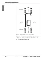
Страница 27: ... take care to ensure that the string inverter is not exposed to wet weather or direct solar irradiation without protection For example it may be advantageous to install the inverter beneath a canopy in order to protect it from unnecessary heat and wetness If you have chosen an inverter with display note that direct sunlight may make reading more difficult Ambient temperature Ideally the ambient te...

Страница 28: ...red by using the wall bracket supplied WARNING Risk of fire Do not expose the inverter to highly inflammable gases No highly inflammable liquids should be stored in the vicinity of the inverter The foundation for installation must be made from a flame retardant material CAUTION Air circulation In order to enable the inverter to be cooled by the ambient air it must be installed vertically No equipm...

Страница 29: ... 5 Tr a n s p o r t a n d in s t a lla t io n ENGLISH Fig 5 1 Air circulation around string inverter If you wish to install a Conergy IPG series string inverter in a switch cabinet take care to ensure sufficient air circulation Do not cover the front of the unit Hot air Cool air ...

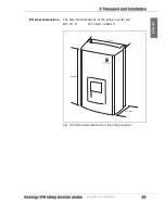
Страница 30: ...e s Instruction m anual 2 9 5 Tr a n s p o r t a n d in s t a lla t io n ENGLISH External dimensions The external dimensions of the string inverter are W x H x D 377 x 620 x 226 mm Fig 5 2 External dimensions of the string inverter 377 mm 620 mm 226 mm ...

Страница 31: ... template and a basic installation equipment pack with wall plugs and screws For wall mounting you will need wall bracket drill template wall plugs and screws from the basic installation equipment pack drill bit 8 mm appropriate open ended spanner Fig 5 3 Wall bracket installation CAUTION Top heaviness Take the considerable top heaviness of the device into consideration during installation Wall mo...

Страница 32: ...t io n ENGLISH 3 Fit the string inverter in place on the wall bracket Fig 5 4 Fitting the string inverter 4 Screw the bottom of the string inverter firmly in place The bottom fixings of the string inverter are both to fix the device in place and also to ensure that it cannot accidentally be pushed off the wall bracket ...

Страница 33: ...3 2 Instruction m anual C o n e r g y IPG s t r in g in v e r t e r s e r ie s 5 Tr a n s p o r t a n d in s t a lla t io n ENGLISH ...

Страница 34: ...phases against zero earth Earthing and short circuiting The background to earthing and short circuiting is that disconnected sections of wiring which do not run in parallel can recharge Cover nearby live parts DANGER A second person must be present during all work on live system parts and leads In the event of an unforeseen electrical accident that person must be able to switch off the power suppl...

Страница 35: ... IPG series string inverter Leave all connections which are not needed sealed as otherwise the string inverter will no longer conform to the requirements of IP 65 protection Keep the sealing plugs When a service is required you can seal the connections off again with the sealing plugs CAN connection If you have chosen the Internet based Conergy SunReader monitoring system connect the Conergy data ...

Страница 36: ...ections of the string inverter 1 CAN In Connection of previous inverter or to Conergy SunReader 2 CAN Out Connection of next inverter A 120 Ω terminator must be installed at the end of a CAN connection 3 AC Out Grid connection 4 CTRL Connection for Conergy IPG easyconnect or external 230 V power supply for the Conergy IPG string vision inverter series inverter display 5 DC Solar system connections...

Страница 37: ...cable must have a cable section of 4 mm2 For devices with AC output of up to 4 6 kW a single string inverter of the Conergy IPG series is used For the operation of systems with higher outputs several string inverters are used These are to be connected so that they are distributed over several phases The wiring of several string inverters is shown in the following diagram Do not connect any consume...

Страница 38: ...e r s e r ie s Instruction m anual 3 7 6 In s t a lla t io n a n d c o m m is s io n in g ENGLISH Fig 6 2 Combination of several string inverters Inverter 3 phase energy meter of the utility Public power grid DC AC DC AC DC AC L1 L2 L3 DC AC ...

Страница 39: ...the end piece 4 Connect the ends of the wire strands to the sockets of the end piece in accordance with the terminal connecting plan 3 Fig 6 4 End piece terminal connecting plan 3 for stripped cable Connecting the mains cable 1 Remove the sheathing from the cable to a length of 35 mm 2 Strip the cable for a length of 9 mm with a wire stripper 3 2 1 N L 2 1 PE earth Neutral wire not used L1 feed ph...

Страница 40: ... s io n in g ENGLISH 5 Tighten the screws on the end piece 3 Fig 6 5 Tightening the screws on end piece 6 Connect the end piece 3 to the connector cap 2 Fig 6 6 Connecting the end piece to the connector cap A clicking sound confirms that the components are correctly connected 7 Screw the nut 1 tightly in place 3 3 2 1 ...

Страница 41: ... and sockets The string inverter is equipped for 2 photovoltaic strings If you want to connect more photovoltaic strings use Multi Contact branch connector plugs and sockets Note the specifications of the string inverter The MC4 connector plugs and sockets are intended for a cable section of 4 to 6 mm2 and an average cable section of 5 5 to 9 mm To connect the solar system to the inverter you can ...

Страница 42: ...ce the cap of the connector plug or connector socket 2 the contact socket 3 and the connector plug 4 or the connector socket 5 to the stripped wire 1 Fig 6 8 Wires with connector plug and socket DANGER Risk of electric shock Disconnect all cables and the plug and socket connection from the power supply Connecting the solar power system 1 Remove the sheathing from the solar cables along max 25 mm 2...

Страница 43: ...ng lugs are aligned against the upper crimping jaw Fig 6 9 Introducing the contact socket to the crimping tool 7 Press the crimping tool firmly together and then open it The contact socket is crimped to the wire Check the socket is firmly in place 1 Stripped wire 4 Connector plug 2 Cap of the connector plug or socket 5 Connector socket 3 Contact socket The contact socket fits in the Diameter 4 gui...

Страница 44: ...tor cap and place the connector socket or connector plug onto the wire Fig 6 10 Connecting the connector socket to the crimped wire 9 Screw the connector cap and the connector socket or connector plug together 10 Tighten the screwed cable gland using the Multi Contact installation wrench Fig 6 11 Tightening the screwed element 11 Repeat the crimping procedure for all wires ...

Страница 45: ...ion cables for this purpose are provided behind the generator junction box All you need to do is draw the cables out to the required length max 5 m and connect them to the connector socket or connector plug of the inverter Please see the Conergy IPG easyconnect generator junction box instruction manual for further information 6 6 Connecting the Conergy SunReader If you have chosen to use the Inter...

Страница 46: ...his is already integrated in the generator junction box If you do not want to connect an external 230 V power supply please leave the sealing plugs in place on the connector 6 8 Connecting Easyconnect If you have decided to use the Conergy IPG easyconnect generator junction box connect the string inverter to this via the CTRL connection see Fig 6 1 page 35 pos 4 of the inverter The CTRL cable is o...

Страница 47: ...ry of the Conergy SunReader If you do not use a Conergy SunReader leave the sealing plugs in place on the connectors 6 10 Connecting the terminator You must install a 120 Ω terminator at the end of a CAN connection The terminator is included in delivery of the Conergy SunReader The terminator is installed as a bus connector between pin 4 CAN high and pin 5 CAN low in an adapter Connecting further ...

Страница 48: ... electronic systems with electric current If the solar irradiation is not sufficient to supply sufficient voltage for the power feed to the grid the Conergy IPG series string inverter automatically reduces its output If there is a fault during commissioning you will find further information in chapter 7 page 49 Illumination or flashing of the LED indicators show the status of the inverter and the ...

Страница 49: ...C internal electronic systems are supplied 30 40 seconds may elapse before test of the LED indicators Internal test of the LEDs Preparation for the power feed to the grid may last 2 3 minutes Preparation of the power feed to the grid connection Audible clicking of the relay Power feed to the grid Grid power available stand by operation of the inverter LED is illuminated LED is flashing LED lights ...

Страница 50: ...wer grid it interrupts the power feed to the grid It switches off The inverter waits 2 minutes before switching back on after a grid failure DC overvoltage If the DC input voltage exceeds the limit value of 800 VDC the inverter interrupts the power feed to the grid It switches off Overheating The Conergy IPG string inverter series inverter is designed to operate at an ambient temperature of up to ...

Страница 51: ...cription of the fault What is the LED indicator or the display showing Is the fault reproducible Information about the PV system such as module type circuitry solar generator voltage How long is the mains cable and what is its cross section What are the irradiation conditions 7 1 LED indicator fault messages The three LED indicators Ready Solar Generator and Grid may be illuminated flashing or fla...

Страница 52: ...s 2 minutes before switching back on after a grid failure Connection audible clicking of the relay Internal electronics systems will not be supplied due to insufficient solar generator voltage Inverter is not supplying power Insulation fault e g earth leakage Internal fault The inverter switches off If the fault arises again the next day it switches itself off again The inverter notes that it is a...

Страница 53: ...faults and diagnostics information The following faults may arise and can be rectified as described If you have any queries please contact Conergy Service LED is off The status of this LED indicator has no significance for the current information displayed Display Possible cause Remedy Over heat i ng Ambient temperature is too high T 60 C The inverter needs cool ambient air Check the installation ...

Страница 54: ...ruction m anual 5 3 7 Tr o u b le s h o o t in g ENGLISH Gr i d i m pedance Grid impedance is too high Check the mains voltage and the grid connection Int er nal f aul t e g fault with the electronics Please contact Conergy Service Display Possible cause Remedy ...

Страница 55: ...5 4 Instruction m anual C o n e r g y IPG s t r in g in v e r t e r s e r ie s 7 Tr o u b le s h o o t in g ENGLISH ...

Страница 56: ...he solar system Next disconnect the various cables from the inverter 3 Secure the disconnector devices against being switching back on Switching off the inverter 1 Switch off the public power supply by means of an external disconnect device 2 Switch off the solar system via an external DC disconnector WARNING Unintentional removal of the plug If the plug is removed while under load it may be damag...

Страница 57: ... pressing the locking clip of the connector plug manually or by using the Multi Contact key 7 Remove the solar cables 8 Seal all connections with sealing plugs 9 Release the two fixing screws on the bottom of the string inverter 10 Remove the string inverter from the wall Take care to ensure that the sealing plugs are correctly in place Otherwise the connections will not be protected against humid...

Страница 58: ...n data MPP voltage range 220 750 V 220 750 V Output in night mode 0 W 0 W Idling voltage 800 V 800 V Switch on voltage 250 V 250 V Max input current 15 2 A 16 2 A Conversion Max efficiency level 96 5 96 7 European efficiency level 95 0 96 0 AC network output data Nominal output 3 400 W 4 600 W Maximum output 3 800 W 5 000 W Rated current 14 8 A 20 0 A Max current 16 5 A 21 7 A Frequency 49 8 50 2 ...

Страница 59: ... Protection type against environ mental factors IP 65 Ambient temperature 10 to 60 C 40 to 60 C with derating Cooling Convection Relative atmospheric humidity max 95 non condensing Mounting type Wall mounted with wall bracket External dimensions W x H x D 377 x 620 x 226 mm Only Conergy IPG string inverter vision series Display type Touch screen Display size W x H 118 x 88 mm 2 DC inputs CAN inter...

Страница 60: ...rgy IPG sizer 4 14 Conergy IPG string vision inverter 19 52 Conergy Service 50 Crimping 36 D DC 14 Directives 6 Display 17 19 52 E Electrical installation 33 External dimensions 29 60 F Fault current monitoring 49 Fault message 49 H Hotline 50 I Included in delivery 25 Installation 30 J Junction box 4 40 45 L LED 47 50 Lightning 14 M Maximum Power Point 17 Monitoring grid 18 MPP tracking 16 O Over...

Страница 61: ...tion m anual C o n e r g y IPG s t r in g in v e r t e r s e r ie s 9 A p p e n d ix ENGLISH R Removal 55 S Specifications 59 Standards 6 Surge protection 17 System planning program 4 W Wall mounting 30 Weight 26 ...

Страница 62: ...IPGSTRING IM ENG 0611 www conergy com Subject to technical modifications without notice 2006 Conergy AG ...

Отзывы: