


145
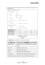
Log
Level
Allows you to configure the event level and filter out unwanted events
below this level. The events ranging from the highest critical level
“Emergency” down to this configured level will be recorded to the log
buffer on the VR-3071 SDRAM. When the log buffer is full, the newer
event will wrap up to the top of the log buffer and overwrite the old
event. By default, the log level is “Debugging”, which is the lowest
critical level.
The log levels are defined as follows:
Emergency = system is unusable
Alert = action must be taken immediately
Critical = critical conditions
Error = Error conditions
Warning = normal but significant condition
Notice= normal but insignificant condition
Informational= provides information for reference
Debugging = debug-level messages
Emergency is the most serious event level, whereas Debugging is the
least important. For instance, if the log level is set to Debugging, all
the events from the lowest Debugging level to the most critical level
Emergency level will be recorded. If the log level is set to Error, only
Error and the level above will be logged.
Display
Level
Allows the user to select the logged events and displays on the View
System Log window for events of this level and above to the highest
Emergency level.
Mode
Allows you to specify whether events should be stored in the local
memory, or be sent to a remote system log server, or both
simultaneously. If remote mode is selected, view system log will not
be able to display events saved in the remote system log server.
When either Remote mode or Both mode is configured, the WEB UI will
prompt the user to enter the Server IP address and Server UDP port.
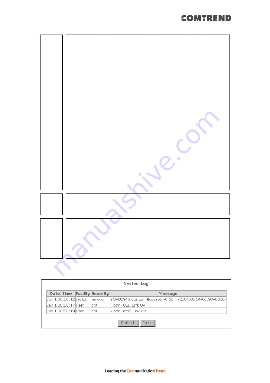
STEP 3: Click View System Log. The results are displayed as follows.
Содержание VR-3071 Series
Страница 1: ...261099 055 VR 3071 Series Home Gateway User Manual Version A1 0 January 10 2020...
Страница 24: ...23 This screen shows hardware software IP settings and other related information...
Страница 31: ...30 ADSL2 Click the Reset Statistics button to refresh this screen...
Страница 42: ...41 4 9 Network Map The network map is a graphical representation of router s wan status and LAN devices...
Страница 46: ...45 5GHz...
Страница 49: ...48 5 GHz Shows the bandwidth that is available for use in each channel Shows interference level in each channel...
Страница 52: ...51 List the associated station to the wireless interface...
Страница 57: ...56 NOTE Up to 16 PVC profiles can be configured and saved in flash memory...
Страница 68: ...67 5 3 3 UPnP Select the checkbox provided and click Apply Save to enable UPnP protocol...
Страница 71: ...70 A maximum of 100 entries can be added to the URL Filter list...
Страница 86: ...85...
Страница 106: ...105...
Страница 130: ...129 2 Both devices need to have the same fixed channel See section 6 12 6 Advanced for details...
Страница 131: ...130 3 Both devices need to have a different fixed access SSID Network Name See section 6 12 1 SSID for details...
Страница 134: ...133 6 12 6 Advanced This page allows you to configure the Physical Wireless interfaces 2 4GHz...
Страница 136: ...135...
Страница 152: ...151 Note Passwords may be as long as 16 characters but must not contain a space Click Save Apply to continue...
Страница 168: ...167 STEP 2 Click the Windows start button Then select Control Panel...
Страница 169: ...168 STEP 3 Select Devices and Printers STEP 4 Select Add a printer...
Страница 189: ...188 F2 2 IP over ETHERNET IPoE IPv4 STEP 1 Select the IP over Ethernet radio button and click Next...
Страница 197: ...196 F2 4 PPP over ATM PPPoA IPv4 STEP 1 Click Next to continue...
Страница 200: ...199 Click Next to continue or click Back to return to the previous step...
Страница 208: ...207 Click Next to continue or click Back to return to the previous step The settings shown above are described below...
Страница 213: ...212 After clicking Apply Save the new service should appear on the main screen...


