8
Front and Rear Panel Features
Before using your Tester, take a few minutes to become familiar with the use of its controls, indicators
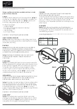
and connectors. The front panel features of the GF-30AC-T are shown in Figure 2-1 and described in
Table 2-1. The rear panel features of the GF-30AC-T are shown in Figure 2-2 and described in Table 2-
2.
Figure 2-1. Controls, Indicators, Connectors - Model GF-30AC-T Front Panel
ITEM NO.
NAME
FUNCTION
1
Green (Pass) Indicator Lamp Incandescent lamp. When lit, indicates that
equipment under test has less than 100 milliohms in
grounding path. Replace with 6.3V type 86 lamp.
2
Red (Fail) Indicator Lamp
Incandescent lamp. When lit, indicates that
equipment under test has more than 100 milliohms
in grounding path or is incorrectly connected to
tester. Replace with 6.3V type 86 lamp.
3
Test Button / Blue Indicator
Lamp
Switch and incandescent lamp. When lamp is lit,
indicates tester power is on and ready to test. When
button is pushed, 25A test is applied to equipment
under test. The test continues for a preset time.
Replace with 14V type 73 lamp.
4
Test Power Receptacle
NEMA 5-15R receptacle. For connection of the
Equipment under test with non-removable power
cord or with 14 AWG test cord provided.
5
Return Lead Receptacle
Isolated banana plug receptacle. The 10 AWG Test
Return Lead provided is connected here.
Table 2-1. Controls, Indicators, Connectors - Model GF-30AC-T Front Panel
Содержание GF-30AC-T
Страница 1: ...GF 30AC T Ground Circuit Tester Instruction Manual...
Страница 3: ...3...


