


disassembly.
2. Completely remove the three thumbscrews that secure the unit cover
assembly (Figure 5-7).
3. Remove the power supply mounting screws (Figure 5-10).
NOTE: If the computer has a cable lock mechanism installed in place of
one of the thumbscrews, see Cable Lock Installation presented
earlier in this section.
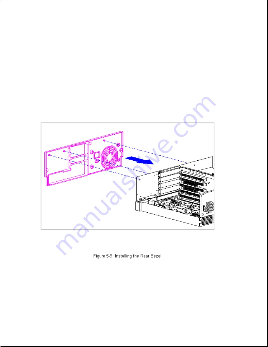
4. If the existing rear bezel is still in place, note the locations of the
snap action tabs (Figure 5-9) and carefully pry the bezel away from the
rear panel of the base pan.
5. To install a rear bezel, align the three snap tabs with their holes in
the rear chassis panel and snap the bezel into place (Figure 5-9).
6. Install the four power supply mounting screws (Figure 5-10) and replace
the unit cover (Figure 5-7). See Section 5.4.4 for installation
procedures if a cable lock is present.
Chapter 5.5 Power Supply
Содержание Prolinea 4100
Страница 92: ...7 Release the wires going to the power switch from the clamps on the base pan Figure 5 14...
Страница 94: ......
Страница 95: ......
Страница 112: ...8 Remove and retain the hard drive mounting bracket Figure 5 33...
Страница 148: ......
Страница 149: ...540 MB IDE Hard Drive Jumper Settings The jumper settings for the 540 MB IDE are shown in Figures 6 9 and 6 10...
Страница 150: ......
Страница 151: ...720 MB IDE Hard Drive Jumper Settings The jumper settings for the 720 MB IDE are shown in Figure 6 11...
Страница 152: ...1 GB IDE Hard Drive Jumper Settings The jumper settings for the 1 GB IDE are shown in Figure 6 12...
Страница 167: ......
Страница 168: ......
Страница 191: ...Table A 2 Mouse Pin Signal 1 Data 2 Unused 3 Ground 4 5 VDC 5 Clock 6 Unused...


