NBLB2 Service Manual
13
6. ACPI (Advanced Configuration and Power Interface)
6.1
Introduction
The Advanced Configuration and Power Interface (ACPI) is a well-specified power
management and configuration mechanism. It evolves the existing collection of
power management codes, APM, PnP BIOS, and Etc.
6.2
ACPI Sleep Status
BIOS must support the following sleep states
– S3, S4 and S5.
6.3
Fast Resume
BIOS must hands off the control to the operating system within the following time
limits:
Required
S3->S0
2seconds
*Measured using the Microsoft BootVis tool.
In addition, total resume time from S3 must be completed within 5 seconds.
6.4
Power State Transition Diagram
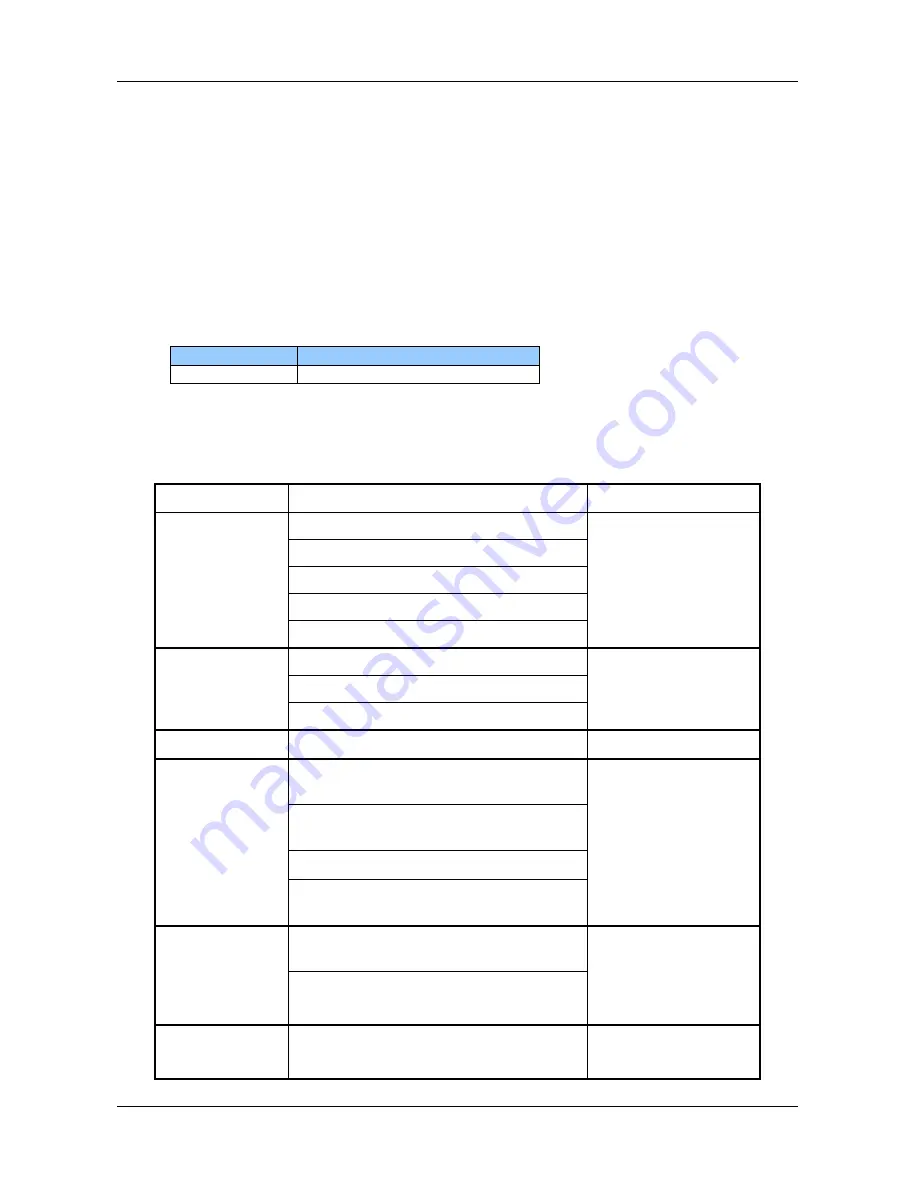
The state transition diagram in ACPI mode is as follows:
From (State)
Leave By Condition
Enter (State)
S3
Power Button
S0
On board LAN
Any key
Alarm
Critical low battery(Only in DC mode)
S4
Power Button
S0
On board LAN (Only in AC mode)
RTC(Only in AC mode)
S5
Power Button
S0
S0
Press Lid switch (depends on ACPI
OS setting)
S3
Standby icon in shutdown menu in
Windows.
ACPI OS timer expired
Critical low battery (depends on
ACPI OS setting)
S0
Press Lid switch (depends on ACPI
OS setting)
S4
Press Power Button (depends on
ACPI OS setting)
S0
Press Lid switch (depends on ACPI
OS setting)
S5
Содержание NBLB2
Страница 1: ...NBLB2 Service Manual...
Страница 6: ......
Страница 7: ...1 Chapter 1 System Description Specification...
Страница 12: ...NBLB2 Service Manual 6 Chapter 2 Software Specification...
Страница 66: ...NBLB2 Service Manual 60 Chapter 3 Hardware...
Страница 69: ...NBLB2 Service Manual 63 Chapter 4 DC DC Converter...
Страница 74: ...NBLB2 Service Manual 68 VOLTAGE IDENTIFICATION CODES...
Страница 75: ...NBLB2 Service Manual 69...
Страница 76: ...NBLB2 Service Manual 70...
Страница 83: ...NBLB2 Service Manual 77 Chapter 5 Disassembly Guide...
Страница 89: ...NBLB2 Service Manual 83 4 Grasp the module and pull it out...
Страница 97: ...NBLB2 Service Manual 91 3 Them remove LVDS cable and microphone cable speaker cable 4 Remove the LCD module...
Страница 100: ...NBLB2 Service Manual 6 Gently lift out the display Remove eight screws securing the hinges to the display...
Страница 103: ...NBLB2 Service Manual 97 3 Lift off the logic upper...
Страница 111: ...NBLB2 Service Manual 97 3 Lift off the logic upper...
Страница 118: ...NBLB2 Service Manual Chapter 6 Testing and Troubleshooting...
Страница 121: ...NBLB2 Service Manual 107 Figure 6 1 Troubleshooting flowchart 1 2...
Страница 122: ...NBLB2 Service Manual Figure 6 1 Troubleshooting flowchart 2 2...
Страница 124: ...NBLB2 Service Manual 3 Power Supply Troubleshooting Figure 6 2 Power Supply Troubleshooting Process...
Страница 129: ...NBLB2 Service Manual 115 4 Display Troubleshooting Figure 6 3 Display troubleshooting process...
Страница 132: ...5 Keyboard Troubleshooting Figure 6 4 Keyboard troubleshooting process...
Страница 134: ...6 External USB Devices Troubleshooting Figure 6 5 External USB device troubleshooting process...
Страница 136: ...7 CRT troubleshooting Figure 6 6 CRT troubleshooting process...
Страница 138: ...8 HDMI troubleshooting Figure 6 7 HDMI troubleshooting process...
Страница 140: ...9 Touch Pad Troubleshooting Figure 6 8 Touch Pad troubleshooting process...
Страница 142: ...10 Speaker Troubleshooting Figure 6 9 Speaker troubleshooting process...
Страница 144: ...11 CD ROM DVD Troubleshooting Figure 6 10 CD ROM DVD drive troubleshooting process...
Страница 146: ...12 Wireless LAN Troubleshooting Figure 6 11 Wireless LAN troubleshooting process...
Страница 148: ...The system board may be damaged Replace it with a new one following the instructions in Chapter...


