Atena Easy Addressable Fire Alarm Panel – Installation and Programming Manual
8
• Use the template in the set to fix the mounting holes of the metal box on the wall.
• Drill holes (suitable for anchors Ø6mm) on the wall and fix the metal box.
• Route the external cables onto the back box, make off connection glands etc., BUT DO NOT make any connections
at this stage. ENTER THE MAINS CABLE THROUGH ITS OWN CABLE ENTRY POINT AND KEEP MAINS WIRING
AWAY FROM SYSTEM AND OTHER LOW VOLTAGE WIRING.
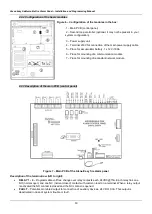
• Connect the mains supply and earth to the power supply terminal (see Figure 16), BUT DO NOT apply the main
electrical supply at this stage.
• Place the battery in an upright position.
• Mount the front cover back to the bottom as mount the hinges in the reverse order of that described on Figure 3.
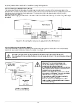
• Connect back the flat cable for the indication and the earthling point (Figure 2).
• Proceed with initial power up of the system and testing.
• When you finish with power up and testing steps and the panel is normal operation mode you must fix the front cover
to the bottom with the two screws from the spare parts kit.
2.2. System Components
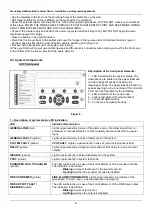
2.2.1 Front panel
Description of the front panel elements:
1
– LED indication for the system status. The
descriptions are printed on the paper label and
can be changed if needed, including for
language change. The paper label is placed in a
special opening on the inner side of the indicator
PCB, over the flat cable for the indication.
2
– LED indication for the used zones
3
– Letters and digits LCD-module (4х40)
4
– Functional digits buttons
5
– Control and navigation buttons
Figure 5
1
– Description of system status LED indication:
LED
Indication/ Description
GENERAL FIRE
(red)
Lights on permanently in case of fire alarm event
– fire alarm signal from an
automatic or manual call point, or other auxiliary device connected to a panel
input.
GENERAL FAULT
(yellow)
Lights on permanently in case of fault event in the system.
SYSTEM FAULT
(yellow)
CPU FAULT
. Lights on permanently in case of main microprocessor fault.
DELAY
(yellow)
Lights on permanently in daytime mode and set time delay for one or several
outputs.
DISABLE
(yellow)
Light on permanently in active disablement in the system.
TEST
(yellow)
Light on permanently in system test mode.
SOUNDERS FAULT/ DISABLED
(yellow)
The LED will be active in case of fault or disablement of the sounders circuits.
The indication is as follows:
-
Blinking
in case of fault event in the sounder circuits.
-
Lighting on
when the sounder circuits are disabled.
FIRE CONFIRMED
(yellow)
FIRE ALARM CONFIRMATION
. Lights on permanently in activation of the
specialized
“In AmC” input – see the description on page 12.
FIRE OUTPUT FAULT/
DISABLED
(yellow)
The LED will be active in case of fault or disablement of the FIRE relay output.
The indication is as follows:
-
Blinking
in case of fault event.
-
Lighting on
when the output is disabled.


