Atena Easy Addressable Fire Alarm Panel – Installation and Programming Manual
15
2.6. Connecting a Heat Printer
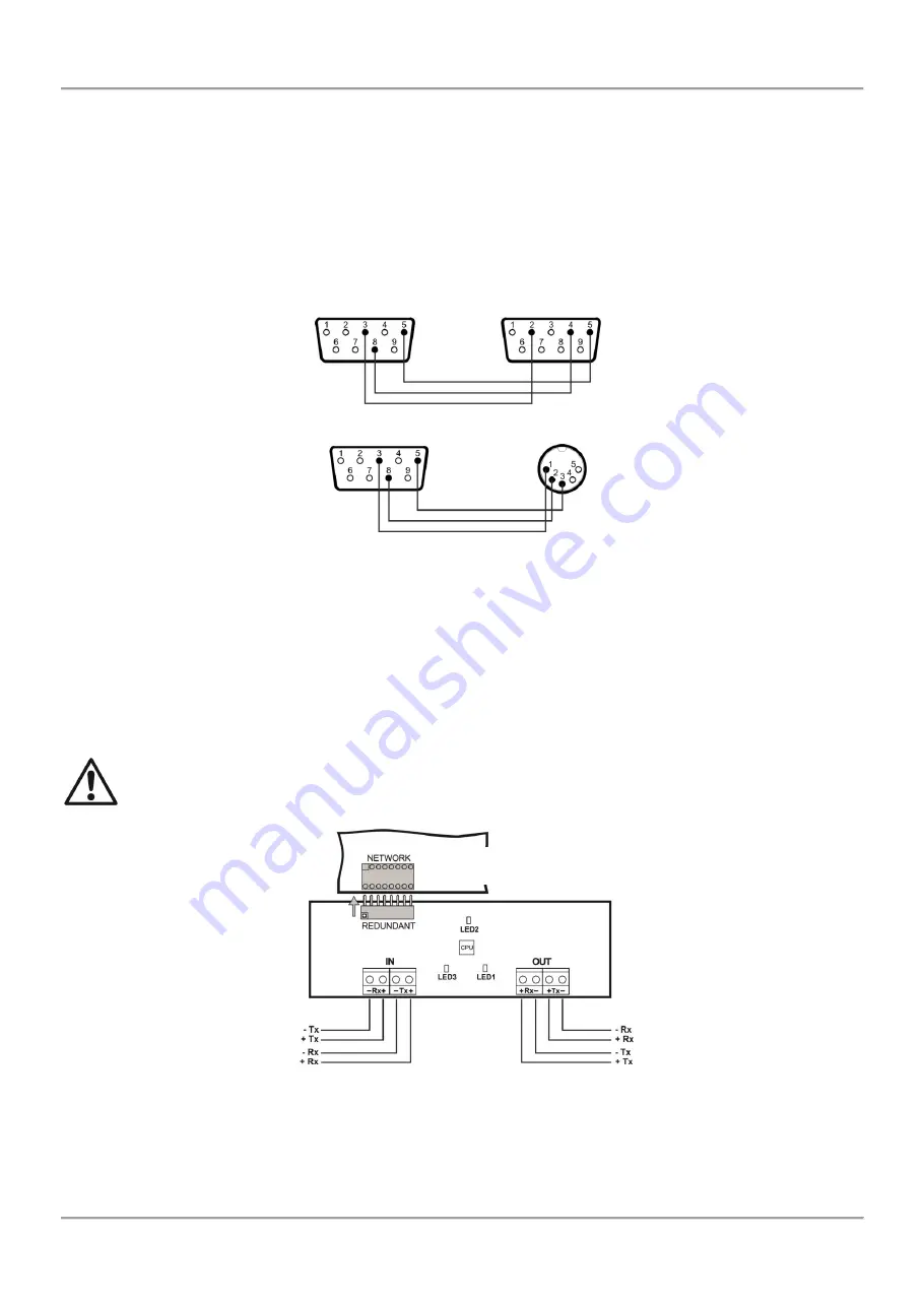
The addressable fire alarm panel Atena Easy is equipped with RS232 interface connector, situated in the middle of the
main PCB, for connecting a heat printer. The heat printer allows the technician to print the log file for the alarm and
fault events, warnings and changes during programming. The capacity of log file is 10000 events, which are saved with
date and time of occurring
– see also item 7.1.4.
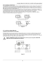
The addressable fire alarm panel Atena Easy supports Canon 9 type external printers, models Kafka and Datecs. For
connecting the Atena Easy panel to the heat printer you have to prepare a special cable for the purpose
– connect two
male DB9-DB9 (Datecs printer) or DB9-DIN5 (Kafka printer) type connectors as shown on Figure 18.
Before printing (access levels 2 and 3)
make sure that the heat printer is connected to the ‘PRINTER’ interface
connector on the main PCB and the printer is powered on.
2.7. Connecting a Network Module
(supported for Soft. Revision 2.8 and higher)
The addressable fire alarm panel Atena Easy is designed with option for connection in a Ethernet network with other
Atena Easy or Atena addressable panels (up to 32). The network module is mounted under the main PCB and is
connected to ‘NET’ connector – Figure 19. The module should be fixed with screws to the metal bottom. The maximum
cable length between two redundant network modules is 1000m.
Attention: NEVER add or remove the network module to the fire panel configuration WHEN THE
MAIN AND BACKUP POWER SUPPLIES ARE ON!
Figure 18
Figure 19
DB9
DB9
DB9
DIN5
To control panel
To Kafka printer
To control panel
To Datecs printer
Atena Easy
Main Board
Module
Redundant
network


