


EQUIPMENT MANUAL FOR TB-1800
TB-1800 QE
Copyright - refer to title page
Page 30
ENU Status : 1-0-0
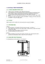
4 COMMISSIONING
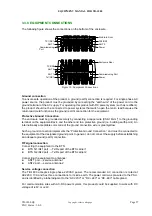
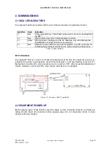
4.1 MCU LED INDICATORS
Four diagnostic LEDs are located on MCU, each indicates the status of a particular function:
Identifier Color Indication
L1
Red
Online programming. This will flash when users read, set or download files
via OMT.
L2
Red
Warning LED, when ON, it indicates alarm condition
L3
Green
MCU operation. Flashing at a rate of 1 flash/sec. Any other flashing rate
indicates MCU is faulty, and has to be replaced.
L4
Red
Wireless modem status. During normal operation, it is OFF, while ON, it’s
indicating faulty wireless modem and no communication will take place.
Table 7: LEDs on MCU
MCU Initialization
The diagnostic LED L2, L3 and L4 will flash simultaneously at the time the equipment is power up,
indicating the system is self-checking. About 60 seconds later, L3 will keep flashing at the rate of 1
flash/second. L2 will be ‘ON’ when any alarm occurs. L4 will turn ‘OFF’, after successful initialization of
modem; otherwise, it will remain ‘ON’, when remote commission is not available.
Figure 13: Location of MCU and LEDs
4.2 EQUIPMENT POWER-UP
Before applying power, check that the expected voltage, current, and power levels do not violate any
ratings. Double check all connections before applying power. Do not manipulate circuits or make
changes with power applied.