SmartLF Cx+40 Instruction Manual
Page 8 of 12
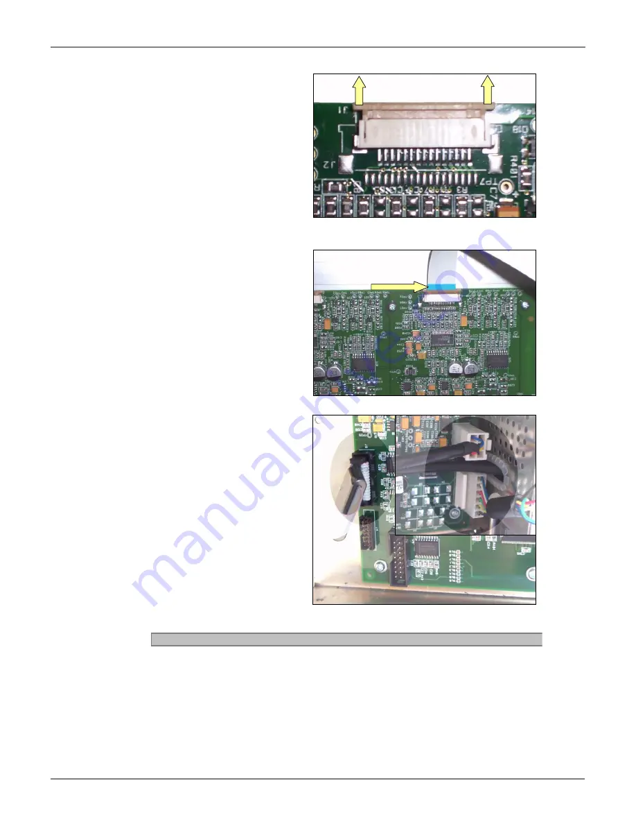
8. Make sure the locking sliders
on the CIS connectors are lifted
up to allow the cable to be
inserted.
9. Making sure the cables are
inserted the correct way
around, insert all 5 of the CIS
ribbon cables into their
adjacent connectors. The
exposed ribbon cores must
face towards the access panel,
so therefore you will see the
blue backing. This is true for
ALL 5 ribbon cables.
10. Re-insert the power Cable PSU
DC O/P from PSU, motor drive
cable and display board ribbon
cable making sure they are
located and positioned
correctly.
11. Close the rear access panel as
described in chapter “1.2
Opening Access Panel.
” page
4.
After fitting the main board, load the dat file that had been saved earlier as described in chapter “0
in chapter “0
1.4
Cx(+)40 Restore Program
12.
” page 12. Or load the dat file send by Colortrac Support. Update the firmware to the
latest as described on page 10, and then run the Normalisation program (page 9) after
all processes are complete.


