


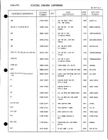


CAUTION:
I f optional fuses are to be used, the fuses next to the Address Select switch must
be removed to prevent damage to the internal ±15V DC supplies.
QDI
0 . 0 0 0 0 °
— 8 9 . 9 9 9 9 °
QD2
9 0 . 0 0 0 0 °
— 1 7 9 . 9 9 9 9 °
QD3
1 8 0 . 0 0 0 0 °
— 2 6 9 . 9 9 9 9 °
QD4
2 7 0 . 0 0 0 0 °
— 3 5 9 . 9 9 9 9 °
Function LEDS and Switches
LEDs
The following LEDs are provided at the top front edge o f the 53A-570 Card to indicate the
status o f the card's operation:
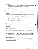
Ouadrant LEDs
Each channel has four quadrant LEDs, labeled QD1, QD2, QD3, and QD4. T h e quadrant
LEDs for a channel indicate the last quadrant programmed f o r that channel. When the
53/63 Series system powers up, the Quadrant LEDs are unlit. T h e y remain u n l i t u n t i l
a channel is programmed. T h e LEDs represent the following quadrants:
Switches
The following switches are provided to select the proper functions f o r the 53A-570 Card's
operating environment:
Halt Switch
This two-position slide switch is located near the card's backplane edge connector. I t
selects the state of the 53A-570 Card after an @XH (Halt) or STOP command is received
by the 53/63 Series System.
a. I f the H a l t Switch is i n the O N position,
then
the 53A-570 Card i s reset t o its
power-up state, a l l parameters are reset t o t h e i r d e f a u l t values, and the Power
LED is lit.
b. I f t h e H a l t S w i t c h i s i n t h e O F F position, t h e n t h e 53A-570 C a r d becomes
unaddressed, the Power L E D is lit, and any programmed parameters o f the card
remain unchanged.
Svnchro/Resolver Switch
Each channel has a two-section rocker switch that configures the channels f o r synchro
or resolver output. Both rocker switches must be set to position C2 for correct operation
of t h e 53A-570 Card. P o s i t i o n C l i s o n l y used w h e n t h e c a r d h a s been f a c t o r y
configured f o r resolver output.
o
570 - 2