


53A-570 DIGITAL/SYNCHRO CARD
•
DESCRIPTION
The 53A-570 Digital/Synchro Card is a printed circuit board assembly for use in a CDS 53/63
Series System. The 53A-570 Card contains one or two programmable 16-bit digital-to-synchro
converters w i t h associated Scott T transformers. E a c h channel can b e independently
programmed from 0 ° t o 359.9999 ° i n steps o f 0.034 °. T h e 53A-570 is programmed b y
transmitting ASCII characters from the system controller to the 53/63 Series System. T h e
ASCII characters transmitted (0.000000 to 0.999999) represent the desired synchro-analog
output angle as a fraction of 360 °.
CONTROLS A N D INDICATORS
The following controls and indicators are provided to select and display the functions of the
53A-570 Card's operating environment.
Address-Select Switch
The 53A-570 Card has a miniature 10-position switch labeled
"ADDRESS" that selects the
53A-570 Card's address
(0-9) i n the 53/63 Series System. T h e switch's cover opens to allow
the address to be reselected. A screwdriver with a
narrow, flat blade should be used to turn
the cam-action wiper to the desired address position.
Power LED
The Power LED provides a valuable diagnostic tool by giving the system programmer a visual
indication o f the action which the system is currently taking. Whenever the 53A-570 is
addressed by the system controller, the Power L E D goes out. T h e L E D remains out until
another function card is addressed. Since only one function card can be addressed at a time,
an unlit Power LED indicates the function card with which the system controller is currently
communicating. T h e Power L E D being l i t not only indicates that the 53A-570 Card is
unaddressed, but that all required dc power (5V dc, ±15V dc) is being supplied.
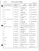
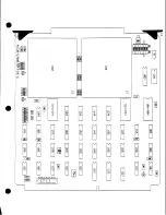
Fuses
The 5V DC, +15V D C and -15V DC power buses each have a fuse that protects the system
from overloads. I f a fuse has blown, the Power LED will not light.
NOTE:
Due to the inrush current caused during power-up, there is a limit of 11
channels of resolvers or synchros allowed per card cage, unless an external
supply is provided for the ±15 volts DC.
For those applications that call for external power, the 53A-570 Card has provisions f o r
connecting an external ±15V D C supply to the card's front-edge connector. T o connect an
external supply, the standard ±15V fuses must be removed from their locations next to the
Address Select Switch and relocated at optional fuse positions at the bottom of the card near
the front-edge connector. T h e pin assignments for the front-edge connector are: + 1 5 V Pins
23 and 24; -15V Pins AA and BB, Ground pins A through Z.
570 - 1